
All products · 35 of 1440
Electronics, sensors, robotics kits, PC components, peripherals — everything Unik Systems carries, in one place.
 Only 1 left
IOT Health Kit
MCU: ESP32 (good ADC/BLE). Sensors: pulse sensor/PPG module, body temp sensor, SpO2 module optional. Data logging: serial/cloud. Power: 5V USB. Educational use, non-clinical.
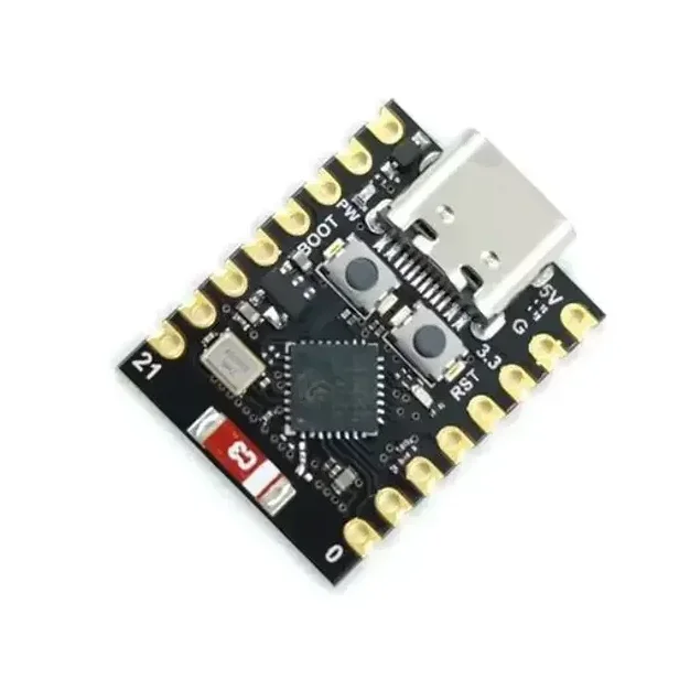
ESP32-C3 Super Mini Development Board With Headers Pins
[ESP Modules] Ultra Compact • Wi-Fi & BLE 5.0 • USB Type-C • Perfect for IoT & Embedded Projects The ESP32-C3 Super Mini Development Board is a compact, feature-rich development board built around the powerful ESP32-C3 SoC from Espressif. Powered by a 32-bit RISC-V single-core processor running at up to 160MHz, it combines 2.4GHz Wi-Fi, Bluetooth 5.0 Low Energy (BLE), and low-power operation in an ultra-small form factor. Designed for IoT, smart home, wireless communication, automation, and embedded system development, the ESP32-C3 Super Mini offers 4MB Flash memory, 400KB SRAM, multiple GPIOs, ADC, PWM, UART, SPI, and I2C interfaces for connecting sensors, displays, relays, and other peripherals. The onboard USB Type-C interface simplifies programming and power supply, while the built-in USB-to-Serial functionality enables quick firmware uploading without requiring additional programmers. Fully compatible with Arduino IDE, ESP-IDF, PlatformIO, and MicroPython, it is suitable for beginners, students, makers, and professional developers. Its ultra-compact breadboard-friendly design makes it ideal for portable and space-constrained projects where performance, wireless connectivity, and energy efficiency are essential. Note: Programming, software configuration, driver installation, firmware flashing, and coding-related issues are not covered under return or replacement. Users are expected to troubleshoot software-related issues independently. ⭐ Features Powerful ESP32-C3 32-bit RISC-V processor CPU frequency up to 160MHz Built-in 2.4GHz Wi-Fi (802.11 b/g/n) Integrated Bluetooth 5.0 Low Energy (BLE) Ultra-compact Super Mini design Breadboard-friendly layout USB Type-C interface for programming and power 4MB onboard Flash memory 400KB SRAM Multiple GPIO, ADC, PWM, UART, SPI & I2C interfaces Low power consumption with Deep Sleep mode Onboard programmable LED Compatible with Arduino IDE, ESP-IDF, PlatformIO & MicroPython Ideal for IoT, automation, robotics, and wireless applications 📋 Technical Specifications Product Type: Development Board Board Model: ESP32-C3 Super Mini Microcontroller: ESP32-C3 Processor Architecture: 32-bit RISC-V CPU Frequency: Up to 160MHz Core: Single Core Flash Memory: 4MB SRAM: 400KB Wi-Fi Standard: IEEE 802.11 b/g/n (2.4GHz) Bluetooth: Bluetooth 5.0 Low Energy (BLE) Operating Voltage: 3.3V Input Voltage: 5V via USB Type-C or 3.3V External USB Interface: USB Type-C GPIO: Multiple Digital GPIO Pins Analog Input: Up to 6 ADC Channels PWM: Supported UART: Supported SPI: Supported I2C: Supported USB-to-Serial: Onboard Onboard LED: User Programmable (GPIO8) Power Consumption: Ultra Low (Deep Sleep ≈ 43µA) Dimensions: Approx. 22.5 × 18 mm Headers: Pre-Soldered 🔧 Applications Suitable for: Internet of Things (IoT) Smart Home Automation Wireless Sensor Networks Home Automation Systems Bluetooth Low Energy Devices Wi-Fi Enabled Controllers Robotics Projects Data Logging Systems Remote Monitoring Industrial Automation Portable Embedded Devices Educational Learning DIY Electronics Projects Wearable Electronics Rapid Prototyping 📦 Package Includes 1 × ESP32-C3 Super Mini Development Board Pin Headers ⚠️ Note Programming, firmware installation, software configuration, and driver-related issues are not covered under warranty, return, or replacement. Please verify board compatibility and install the appropriate development environment before programming. Soldered and non-soldered header pin depend on stock
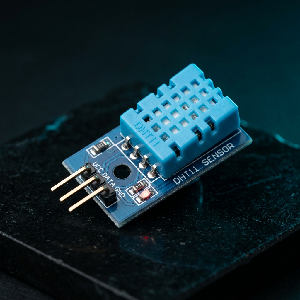
DHT11 Digital Temperature and Humidity Sensor Module 3.3V-5V for Arduino & Raspberry Pi
[Temperature Sensor] The DHT11 Digital Temperature and Humidity Sensor Module is a reliable and cost-effective sensor designed to measure ambient temperature and relative humidity. It combines a capacitive humidity sensing element and a thermistor with a built-in digital signal processing unit, providing calibrated digital output directly to microcontrollers. In addition, the DHT11 offers stable performance and excellent long-term reliability, making it suitable for environmental monitoring and automation applications. As a result, it is widely used in weather stations, smart home systems, greenhouse monitoring, HVAC systems, and educational electronics projects. Because the module includes the required pull-up resistor, interfacing with microcontrollers becomes simple and straightforward. Furthermore, only three connections are required: VCC, GND, and Data Output. The sensor operates from a wide voltage range of 3.3V to 5.5V DC, ensuring compatibility with Arduino, Raspberry Pi, ESP32, STM32, NodeMCU, and other development boards. Moreover, readily available libraries and example codes allow quick integration into projects. The DHT11 utilizes advanced digital signal acquisition technology and dedicated temperature-humidity sensing techniques to ensure accurate and dependable measurements. 🔹 Key Features Measures temperature and humidity simultaneously Calibrated digital signal output Low power consumption High reliability and long-term stability Capacitive humidity sensing technology Built-in pull-up resistor on module Compatible with Arduino, ESP32, Raspberry Pi, and STM32 Simple 3-wire interface Easy integration into IoT projects Compact and lightweight design 🔹 Technical Specifications Sensor Model: DHT11 Operating Voltage: 3.3V – 5.5V DC Output Type: Digital Serial Output Humidity Measurement Range: 20%RH – 90%RH Humidity Accuracy: ±5%RH Humidity Resolution: 1%RH Temperature Measurement Range: 0°C – 50°C Temperature Accuracy: ±2°C Temperature Resolution: 1°C Sampling Rate: 1Hz (One Reading Per Second) Long-Term Stability: < ±1%RH/Year Interchangeability: Fully Interchangeable Sensor Technology: Capacitive Humidity Sensor + Thermistor 🔹 Pin Configuration Pin 1 (VCC): 3.3V – 5.5V DC Power Supply Pin 2 (DATA): Digital Serial Data Output Pin 3 (GND): Ground 🔹 Applications This sensor module is suitable for: Arduino projects Raspberry Pi projects ESP32 projects IoT systems Weather monitoring stations Smart home automation Greenhouse monitoring HVAC control systems Environmental monitoring Educational electronics projects 🔹 Package Includes 1 × DHT11 Digital Temperature and Humidity Sensor Module
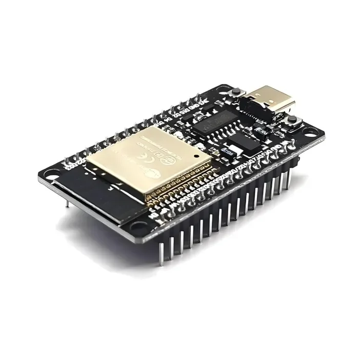
ESP32 Development Board with WiFi & Bluetooth – CH340C USB Type-C
[ESP Modules] The ESP32 Development Board with WiFi & Bluetooth (CH340C, Type-C) is a powerful and versatile microcontroller board designed for modern wireless and IoT applications. It features a dual-core processor and integrated 2.4GHz WiFi and Bluetooth (Classic + BLE) connectivity. This board includes an onboard CH340C USB-to-Serial converter, which allows easy programming and communication without requiring an external crystal oscillator. The USB Type-C port provides a stable and reversible connection for power and data. With a wide range of GPIO pins and peripherals such as ADC, DAC, PWM, UART, SPI, and I2C, this board is perfect for building home automation systems, smart devices, IoT nodes, robotics controllers, sensor networks, web servers, and wireless projects. It is fully compatible with Arduino IDE, ESP-IDF, and MicroPython, making it suitable for beginners, students, and professional developers. 🔹 Key Features Based on ESP32 dual-core microcontroller Built-in WiFi 802.11 b/g/n and Bluetooth v4.2 (Classic + BLE) Onboard CH340C USB-to-Serial converter (no external crystal required) Modern USB Type-C connector for power and programming Dual-core CPU up to 240 MHz for high-performance applications Multiple GPIO pins with ADC, DAC, PWM support Supports Arduino IDE, ESP-IDF, and MicroPython Low-power modes including deep sleep for battery-powered projects Compact design with breadboard-friendly layout Ideal for IoT, automation, robotics, smart home, and DIY electronics 🔹 Technical Specifications Microcontroller: ESP32 CPU: Dual-core Tensilica LX6, up to 240 MHz Flash Memory: 4 MB (typical, may vary by batch) SRAM: 520 KB Wireless Connectivity: WiFi: 2.4 GHz, 802.11 b/g/n Bluetooth: v4.2, Classic + BLE USB Interface: USB Type-C USB-to-Serial Chip: CH340C Operating Voltage: 3.3 V Input Voltage: 5 V via USB Logic Level: 3.3 V GPIO Pins: 30+ multifunction pins Peripherals: ADC, DAC, PWM, UART, SPI, I2C, I2S Clock Frequency: Up to 240 MHz Programming Support: Arduino IDE, ESP-IDF, MicroPython Onboard Components: Reset & Boot buttons, voltage regulator, status LEDs Form Factor: Standard ESP32 Dev Board size 🔹 Applications Internet of Things (IoT) projects Home and industrial automation Smart home devices Robotics and motor control Wireless sensor networks Web servers and cloud-connected devices Educational and training projects DIY electronics and prototyping 🔹 Package Contents 1 × ESP32 Development Board with WiFi & Bluetooth (CH340C, USB Type-C)
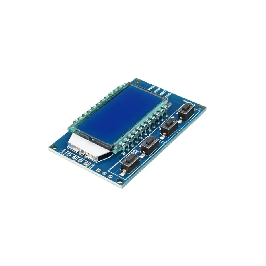
XY-LPWM Signal Generator PWM Pulse Frequency Duty Cycle Adjustable Module LCD Display Module
XY-LPWM Signal Generator PWM Pulse Frequency Duty Cycle Adjustable Module LCD Display Module is a two-channel PWM signal generator. It has dedicated switches for adjusting the frequency and duty cycle separately. Using this module PWM output, frequency and duty cycle can be set as per requirements. Communication Standard: 9600 bps Data bits: 8 Stop bit: 1 Check digit: none Flow control: none Set the frequency of the PWM “F101”: Set the frequency to 101 Hz (001 to 999) “F1.05”: set the frequency of 1.05 kHz (1.00 ~ 9.99) “F10.5”: Set the frequency to 10.5kHz (10.0 ~ 99.9) “F1.0.5”: set the frequency of 105kHz (1.0.0 ~ 1.5.0) Set the PWM duty cycle “DXXX”: set the PWM duty cycle to XXX; (001 ~ 100) Such as D050, set the PWM duty cycle is 50% Read the set parameters Send a “read” string to read the set parameters. Set successfully return: DOWN; Setup failed to return: FALL. Application: This is used to drive a stepper motor driver’s square wave. Generate an adjustable pulse for MCU. Generate an adjustable pulse for controlling relative circuit (PWM adjust lightspeed, etc). Used as a square wave signal generator for experimental development and use. Parameter Settings: The module has 4 switches, two for frequency adjustment and two for duty cycle adjustment. This module can generate frequencies between 1Hz and 150kHz, with automatic switching for different ranges. Frequency is divided into four ranges, automatic switching: 1. XXX (no decimal point): the smallest unit is 1Hz, the value range of 1Hz ~ 999Hz; 2. X.XX (decimal point in the hundred) the smallest unit is 0.01Khz, the range of 1.00Khz ~ 9.99Khz; 3. XX.X (decimal point in ten): the smallest unit is 0.1Khz; value range of 10.0KHz ~ 99.9KHz 4. X.X.X (decimal point in ten and hundred): the smallest unit is 1Khz; value range 1KHz ~ 150KHz 5. e.g. frequency display: 100 indicates PWM output 100Hz pulse; 1.01 indicates PWM output 1.01K pulse; 54.1 indicates that the PWM output has a pulse of 54.1 kHz; 1.2.4 indicates that the PWM output is 124 kHz pulse; Duty cycle range: 1 – 100%. In case of a power outage or if the module is powered down, the parameters that are set are saved automatically, so there is no need to set the parameters again. Single touch for increasing or decreasing single unit and long press for fast increasing or decreasing. Features: LCD display for frequency and duty cycle. Wide frequency range. High precision. Serial communication(TTL based). Package Includes: 1 x XY-LPWM Signal Generator PWM Pulse Frequency Duty Cycle Adjustable Module LCD Display Module.
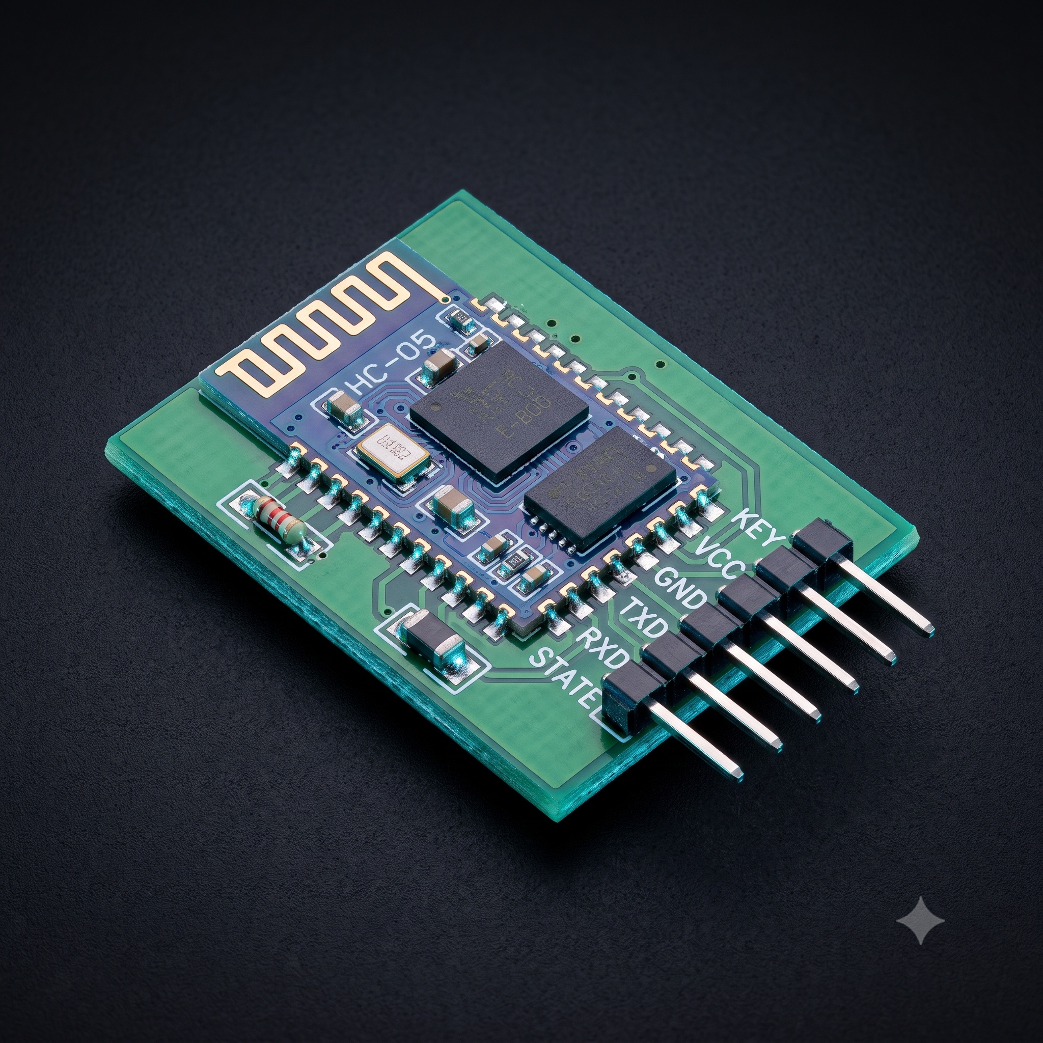
HC-05 6pin Bluetooth Module with Button
[Bluetooth Module] HC-05 Bluetooth Module Are you in search of an HC-05 Bluetooth Module, a versatile and cost-effective solution for your wireless communication needs? Look no further. This Bluetooth module offers seamless wireless communication for a wide range of applications, from GPS navigation systems to water and electricity meter readings. Whether you're an electronics enthusiast, a DIY hobbyist, or a professional looking for competitive pricing, this module is designed to meet your requirements. The HC-05 Bluetooth Module lets you switch between Master and Slave modes with ease using AT Commands, and it comes pre-configured in Slave Mode. Its compatibility with devices such as phones, laptops, and microcontrollers ensures hassle-free connectivity. With a USART interface, it's a perfect fit for microcontrollers supporting USART communication. Plus, you can configure its settings effortlessly using the command mode. Ideal for DIY projects and data exchange, this Bluetooth module provides LED feedback for seamless operation, giving you the best bang for your buck. Buy the HC-05 Bluetooth Module today and enjoy top-notch wireless communication at a competitive price. The HC-05 Bluetooth Module with Baseplate is a slave-only device. This means that it can connect to most phones and computers with Bluetooth but it cannot connect to another slave-only device such as keyboards and other HC-06 modules. To connect with other slave devices a master module would be necessary such as the HC-05 module ,which can do both master and slave. The slave mode in HC-05 Bluetooth cannot initiate a connection to another Bluetooth device but can accept connections. Master mode can initiate a connection to other devices. Key Features: Working current: matching for 30 mA, matching the communication for 8 mA. With the computer and Bluetooth adapter, PDA, seamless connection equipment. Use the CSR mainstream Bluetooth chip, Bluetooth V2.0 protocol standards. Potter default rate of 9600, the user can be set up. Bluetooth protocol: Bluetooth Specification v2.0+EDR Speed: Asynchronous: 2.1Mbps(Max) / 160 kbps, Synchronous: 1Mbps/1Mbps. Security: Authentication and encryption. Profiles: Bluetooth serial port. HC-05 Bluetooth Module Pin Diagram: HC-05 Bluetooth Module Pin Description: Pin Number Pin Name Description 1 Enable / Key This pin is used to switch between command mode (set low) and Data Mode (set high). The default setting of this HC 05 Bluetooth module is Data Mode. 2 Vcc This pin can be used to power the Bluetooth module. It has an operating voltage of +5V DC. 3 Ground Connect the module's ground pin to the Microcontroller’s Ground Pin (GND). 4 TX – Transmitter Sends serial data to the MCU. This pin will distribute all Bluetooth data in the form of serial data to the Microcontroller. 5 RX – Receiver Obtain Serial Data. This pin will transmit all serial data that is provided to it over Bluetooth. 6 State The on-board LED attached to the state pin can be used as feedback to see if Bluetooth is functioning properly. 7 LED Indicates the status of Module Blink once in 2 sec: Command Mode Repeated Blink: Waiting for connection in Data Mode Blink twice in 1 sec: Connection successful in Data Mode 8 Button Used to control the Key/Enable pin to switch between Data Mode and command Mode HC-05 Default Values: Bluetooth Name: “HC-05” Password: 1234 or 0000 Communication: Slave Mode: Data Mode Data Mode Baud Rate: 9600, 8, N, 1 Applications Can be used for wireless communication between two microcontroller units. Communicate with Laptop mobile phones etc. Data Logging Wireless Robots DIY Home Automation Projects GPS-based DIY projects. Specifications: Serial communications 9600-115200bps Frequency 2.4~2.524 GHz Power Supply 5VDC Operating Current 30mA Range <100m Dimensions 30mm x 14mm x 2.2 mm Weight 5 grams Package Includes: 1 x HC-05 Bluetooth Module
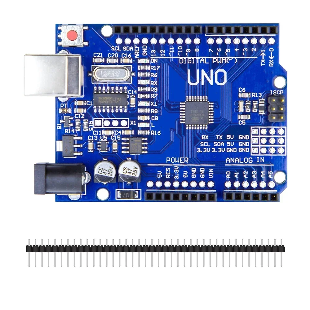
Arduino Uno R3 CH340G ATMega328P Development Board Compatible with Arduino
[Arduino Boards, Development Board] Product Description The Uno R3 CH340G ATmega328p Development Board is the low-cost version of the popular Uno R3 Arduino. It is assembled with the CH340 USB to Serial converter chip, instead of using an Atmega16U2 chip. We have used plenty of these low-cost Arduino boards with CH340 chips, and have found them to work perfectly. The only time the CH340 chip is used is during programming and when using the serial output of the USB port. During normal operation, this board is identical to the more expensive version without CH340 chip. Features The Arduino Uno R3 is a micro-controller board base on the ATmega328 . It has 14 digital input/output pins (of which 6 can be used as PWM outputs); 6 analog inputs, a 16 MHz ceramic resonator, a USB connection, a power jack, an ICSP header, and a reset button. It contains everything need to support the micro-controller; simply connect it to a computer with a USB cable or power it with a AC-to-DC adapter or battery to get start. The Arduino Uno R3 differs from all preceding boards in that it does not use the FTDI USB-to-serial driver chip. Instead, it features the Atmega16U2 (Atmega8U2 up to version R2) program as a USB-to-serial converter. Revision 2 of the Uno board has a resistor pulling the 8U2 HWB line to ground, making it easier to put into DFU mode. Note: The Arduino Uno R3 reference design can use an Atmega8, 168, or 328, Current models use an ATmega328, but an Atmega8 is shown in the schematic for reference. The pin configuration is identical on all three processors. Package Includes 1 x Arduino Uno R3 CH340G ATMega328P Development Board
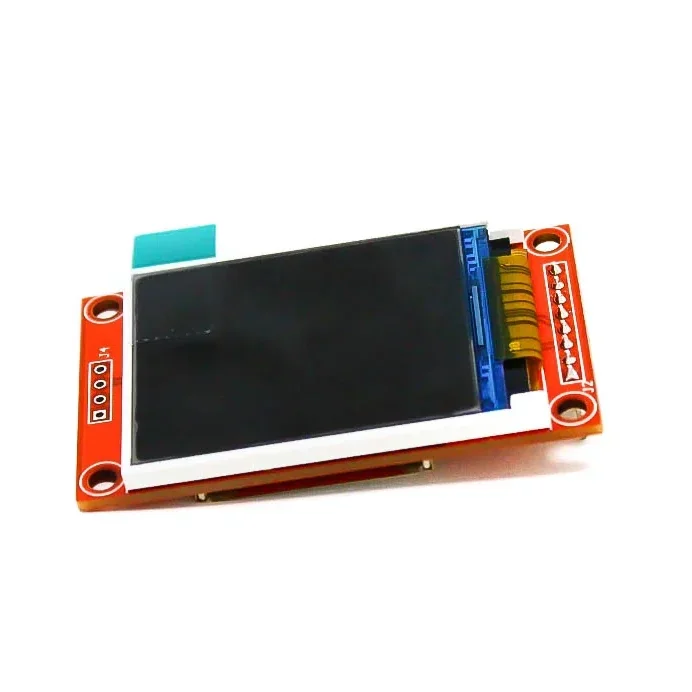
1.8 Inch TFT LCD Module 128 x 160 with SPI
[LED/LCD Display Module] Since the 1.8 Inch TFT LCD Module display uses 4-wire SPI to communicate and has its own pixel-addressable frame buffer, it can be used with every kind of microcontroller. Even a very small one with low memory and few pins available! The 1.8″ display has 128×160 colour pixels. Unlike the low cost “Nokia 6110” and similar LCD displays, which are CSTN type and thus have poor colour and slow refresh, this display is a true TFT! The TFT driver (ST7735R) can display full 18-bit colour (262,144 shades!). And the LCD will always come with the same driver chip so there are no worries that your code will not work from one to the other. The breakout has the TFT display soldered on (it uses a delicate flex-circuit connector) as well as an ultra-low-dropout 3.3V regulator and a 3/5V level shifter so you can use it with 3.3V or 5V power and logic. We also had a little space so we placed a microSD card holder so you can easily load full-colour bitmaps from a FAT16/FAT32 formatted microSD card. For more displays click below, LED/LCD Display Features : 1.8-inch serial SPI colour display module Support analogue SPI and hardware SPI The LCD has a wide viewing angle, the contrast is also very suitable. Good quality display. Package includes: 1 x 1.8 Inch TFT LCD Module 128 x 160 with 4 IO
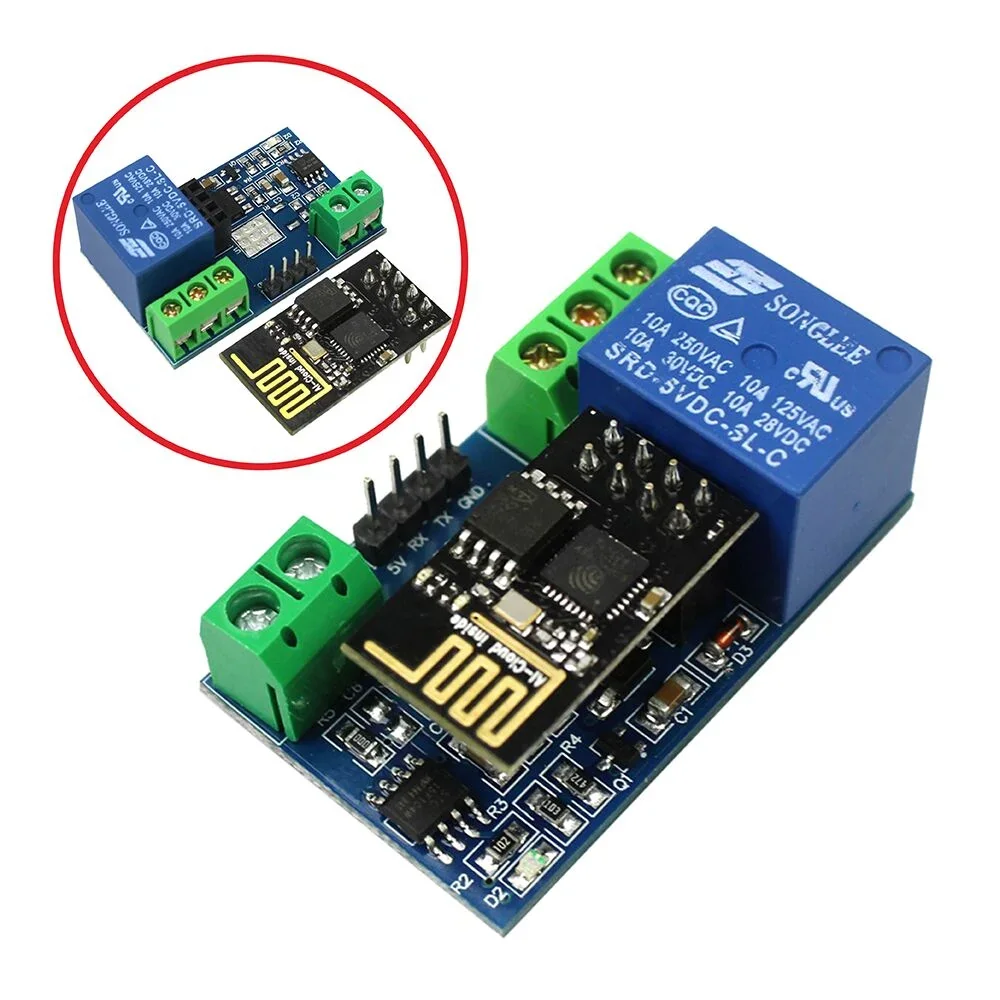
ESP8266 WiFi 5V 1 Channel Relay Module Good Quality
[Relay Module] General Info : Onboard ESP8266 WIFI module, AP mode can be connected at the same time 5 client The module has two ways to work: (i) mobile phone directly mounted on the WIFI module; (ii) mobile phone and WIFI module also carried on the router. How to use : Onboard ESP8266 WIFI module has three operating modes: STA (client), AP (hot), STA + AP (client + hot), according to the work of the module to select the corresponding WIFI module mode of operation The The module needs to use the serial debugging software on the computer and USB to TTL module to send AT commands to configure the WIFI module, USB to TTL module RX, TX, GND pin, then the module on the TX, RX, GND pin, IN +, IN – 5V power supply. Usage Instructions 1) Hardware Connection: Insert the pre-programmed ESP-01/01S module into the onboard 2×4 pin female header (as shown in the diagram below). 2) Power Supply : Connect a DC 5V-12V power source to the module, with the positive terminal to VCC and the negative terminal to GND. 3) Mobile WiFi Connection : Open your phone's WLAN settings, search for and connect to the ESP8266-XXXX hotspot (default password: 12345678). 4) Launch Control APP : Run the pre-installed ESP8266 Controller application on your Android phone. 5) Configure IP Address : Enter the default IP address: 192.168.1.1 in the APP to remotely control the relay switch via your phone. Transmission distance: Open environment, the mobile phone mounted on the WIFI module when the maximum transmission distance of 400m. When the WiFI module and mobile phone at the same time carried on the router when the transmission distance according to the router’s signal weakly; Board function description : IN +, IN-: 5V power input; TX, RX, GND: Serial debug pin; Onboard the ESP8266 WIFI module has three work modes: STA (client), AP (hot), the STA + Ap( hot +client), according to the workings of a module to the corresponding choice of WIFI module working mode. Module need before use serial debugging software and USB to TTL module send serial command was carried out on the WIFI module configuration (don’t power outages after configuration is complete, as some of the parameters of WIFI module cannot be saved when the power is cut off), mobile phone and WIFI module after establishing a network connection can use the phone APP control relay. Control Commands : When cell phone equipped with WiFi module sends commands in the following order: (The default baud rate 115200) AT+CWMODE=2, namely AP mode is selected. AT+RST, reset. AT+CIPMUX=1, open multiple connections. AT+CIPSERVER=1,8080, configure the TCP server, set the port. AT+CIOBAUD=9600 set the baud rate to 9600. (working in relays to control the baud rate 9600). AT+CIFSR to view the AP mode IP address, such as the APIP, “192.168.4.1”. Cell phone WIFI signal connection name starts with AI-THINKER or ESP8266. In the “TCP connection” address and port into the APP, such as 192.168.4.1 and 8080. Click on the grey box relays can be controlled. Features: Onboard Module: ESP8266 wifi module; in AP mode it can connect with 5 Clients at the same time Operating Way: cellphone carried on wifi module; cellphone and wifi module carried on the same router, and use the APP to control relay Diode effusion protection. Short response time
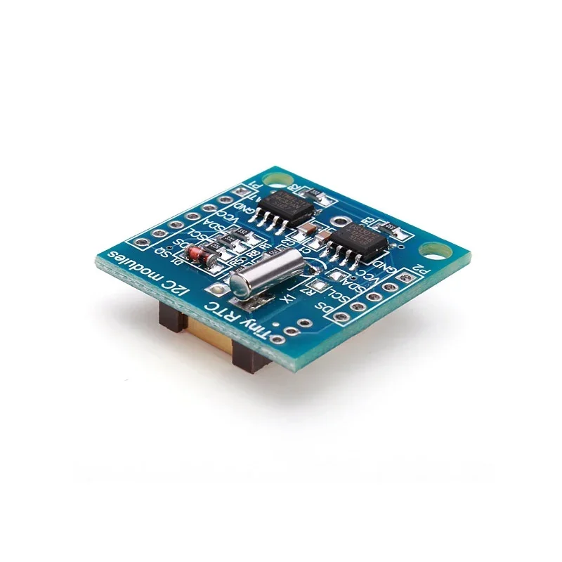
RTC Real Time Clock DS1307 I2C IIC Module for Arduino
[Clock Module, Sensors] This is Tiny RTC Real Time Clock DS1307 I2C IIC Module for Arduino. It contains a DS1307 real-time clock IC with a backup battery. It’s one of the easiest to use RTCs out there, with Arduino and other libraries or simply use I2C commands to set and retrieve the time and date. Includes a lithium coin cell battery which should be good for four years at least. Along with the DS1307 real-time clock, the module also has an Atmel 24C32 EEPROM chip which is handy for storing data without worrying about power loss. There is also space on the board to solder your own DS18B20 temperature sensor. This battery-powered clock allows you to keep a reasonably accurate time even when your Arduino is powered off. It is very useful in data logging and other time-sensitive applications. The device uses I2C to communicate with your Arduino. Features : Two-wire I2C interface Hour: Minutes: Seconds AM/PM Leap year compensation Accurate calendar up to the year 2100 Consumes Less than 500nA in Battery-Backup 1Hz output pin 56 Bytes of Non-volatile memory available to the user 4KB of serial electrically erasable and programmable read-only memory (EEPROM) Embed DS18B20 temperature sensor interface with the pull-up resistor.
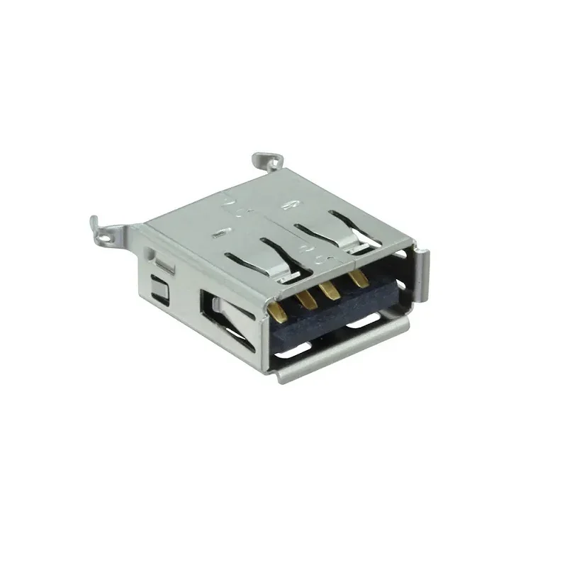
USB Connector, USB Type A, USB 2.0, Receptacle, 4 Ways, PCB Mount
[USB Socket] This is a USB Type A Female Solder Jacks Connector PCB Socket. It complies with the Universal Serial Bus implementers forum. Multiple devices can be connected to this connector. Features: Durable. Robust. Supports USB 2.0 hardware. Package Includes: 1 x Amphenol USB Connector, USB Type A, USB 2.0, Receptacle, 4 Ways, PCB Mount
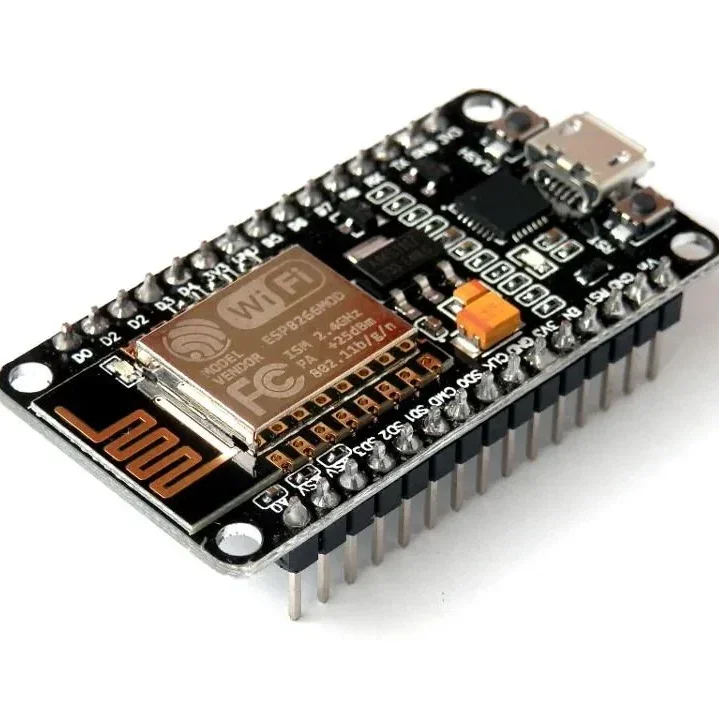
ESP8266 NodeMCU CP2102 ESP-12E WiFi Development Board
[ESP Modules] ESP8266 NodeMCU CP2102 ESP-12E WiFi Development Board ESP8266 ESP-12E • CP2102 USB Interface • Built-in WiFi • Arduino & Lua Compatible • IoT Development Board The ESP8266 NodeMCU CP2102 ESP-12E WiFi Development Board is a compact and powerful development board designed for IoT (Internet of Things), wireless communication, home automation, robotics, and embedded system projects. Based on the highly popular ESP8266 ESP-12E WiFi module, it combines a 32-bit microcontroller, WiFi connectivity, and a CP2102 USB-to-Serial interface on a single breadboard-friendly board. The board comes preloaded with NodeMCU firmware, allowing easy programming using Lua scripting, while also offering full compatibility with the Arduino IDE, making it suitable for both beginners and advanced developers. With integrated 802.11 b/g/n WiFi, TCP/IP networking, multiple GPIO pins, PWM, I2C, SPI, and UART interfaces, it provides everything required for rapid IoT prototyping and wireless application development. The onboard CP2102 USB interface, 3.3V voltage regulator, and logic-level conversion circuitry allow direct connection to a computer for programming and power, eliminating the need for external USB-to-Serial converters. ⭐ Features ESP8266 ESP-12E WiFi module Built-in CP2102 USB-to-Serial interface 802.11 b/g/n WiFi connectivity Integrated TCP/IP protocol stack 32-bit processor with onboard memory Compatible with Arduino IDE, Lua, and NodeMCU firmware Breadboard-friendly compact design Multiple GPIO pins Supports PWM, I2C, SPI, and UART Onboard 3.3V voltage regulator Logic-level conversion circuitry included Low power consumption Ideal for IoT and wireless projects Easy plug-and-play programming 📋 Technical Specifications Product Type: WiFi Development Board Model: ESP8266 NodeMCU ESP-12E Microcontroller: ESP8266EX WiFi Standard: IEEE 802.11 b/g/n USB Interface: CP2102 Operating Voltage: 3.3V Input Voltage: 5V via Micro USB Flash Memory: 4MB CPU: 32-bit Tensilica L106 Clock Frequency: 80MHz / 160MHz GPIO Pins: Multiple Digital I/O Communication Interfaces: UART, SPI, I2C PWM Support: Yes ADC: 1 Channel (10-bit) USB Connector: Micro USB Firmware: NodeMCU (Preloaded) Programming Support: Arduino IDE, Lua, ESP8266 SDK Board Size: Approx. 58 × 31 mm 🔧 Applications IoT (Internet of Things) Projects Home Automation Smart Lighting Systems WiFi Sensor Nodes Wireless Data Logging Robotics Projects Arduino WiFi Projects ESP8266 Development Remote Monitoring Systems MQTT Applications Web Server Projects Smart Agriculture Industrial Automation DIY Electronics Educational Projects 📦 Package Includes 1 × ESP8266 NodeMCU CP2102 ESP-12E WiFi Development Board ⚠️ Note Operates at 3.3V logic levels. Install the CP2102 USB driver if the board is not detected by your computer. Use a good quality Micro USB cable for programming and power. Product appearance may vary slightly depending on the manufacturing batch.
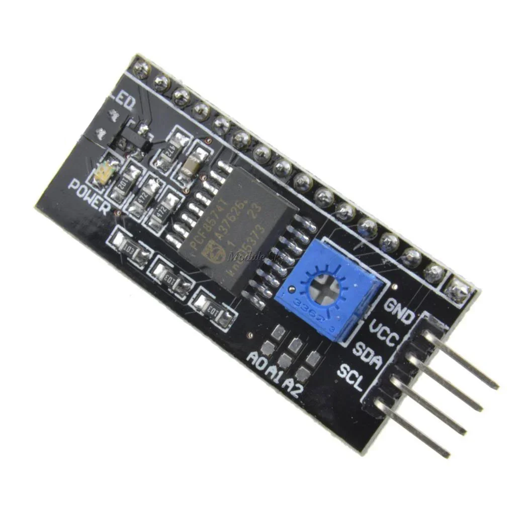
IIC/I2C Serial Interface Adapter Module ( Made In India)
[LED/LCD Display Module] This is a RoHS compliant I2C Serial LCD Daughter board that can be connected to a standard 16×2 or 20×4 Character Display Module that supports 4-bit mode. All Character Modules sold on our site support 4-bit mode, and nearly all commercially available 16×2 and 20×4 line character modules support it too. This board has a PCF8574 I2C chip that converts I2C serial data to parallel data for the LCD display. There are many examples on the internet for using this board with Arduino. Do a search for “Arduino LCD PCF8574“. The I2C address is 0x3F by default, but this can be changed via 3 solder jumpers provided on the board. This allows up to 3 LCD displays to be controlled via a single I2C bus (giving each one it’s own address) Specifications and Features: 5V power supply. Serial I2C control of LCD display using PCF8574. Backlight can be enabled or disabled via a jumper on the board. Contrast control via a potentiometer. Can have 8 modules on a single I2C bus (change address via solder jumpers)address, allowing. Size :41.6 x 19.2 mm. Package Includes: 1 x IIC/I2C Serial Interface Adapter Module
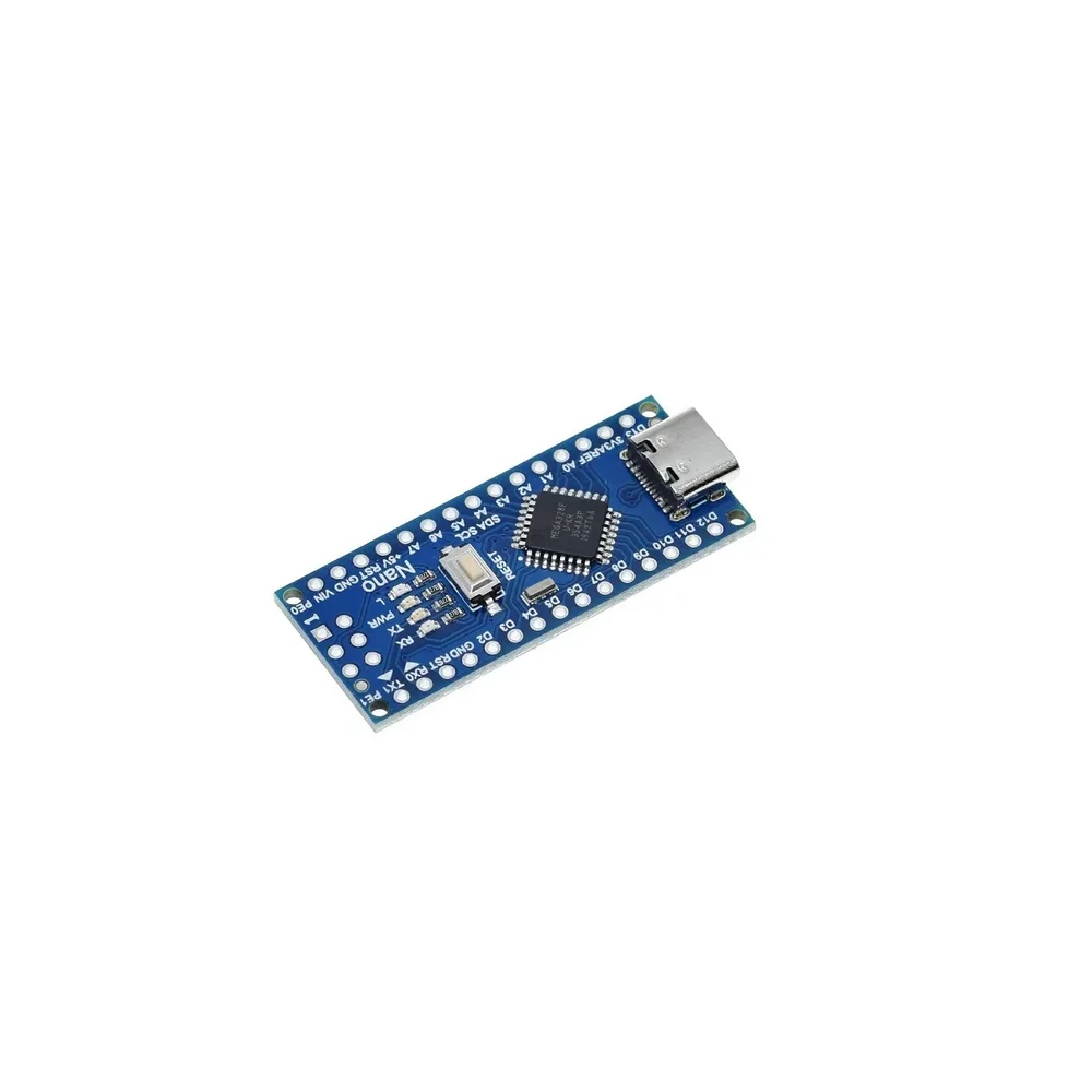
Unsoldered Nano V3.0 ATmega328P 5V 16MHz CH340 Type-C
[Arduino Boards] This Arduino-compatible Nano V3.0 micro-controller is a small, complete, micro-controller board based on the ATmega328 MCU. It has more or less the same functionality as the Arduino Duemilanove, but in a smaller package. It lacks only a DC power jack, and uses the more compact Mini USB (Mini-B) connector instead of a standard USB connector. It is compatible with Arduino programs and the Arduino IDE. This version of the Nano uses the CH340G USB interface controller. It can be powered via the Mini-B USB connection, a 6-20V unregulated external power supply (pin 30), or 5V regulated external power supply (pin 27). The power source is automatically selected to the highest voltage source. Features: CH340G USB bus converter chip replaces FT232RL Operating Voltage(logic level): 5V 8 analog inputs ports: A0 – A7 14 Digital input / output ports: TX, RX, D2 – D13 6 PWM ports: D3, D5, D6, D9, D10, D11 1 pair of TTL level serial transceiver ports: RX / TX Uses Atmel Atmega328P-AU MCU with bootloader installed Support USB download and Power over Mini-B Mini USB connector Recommended input voltage: 7V – 12V DC on pin 30 or 5V on pin 27 Maximum input voltage limits: 6V – 20V Supports ISP download Supplied with connector pins (headers), not soldered to the board for user flexibility Package Includes: 1 X Nano V3.0 16MHz CH340
 Out of stock
ESP-12E: ESP8266 Serial Port WIFI Wireless Transceiver Module For Arduino
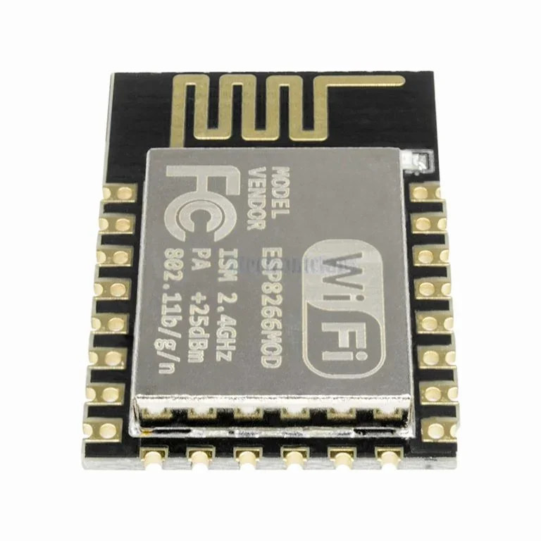
[ESP Modules] This is ESP-12E: ESP8266 Serial Port WIFI Wireless Transceiver Module For Arduino. This small WIFI transceiver is the perfect solution for home Automation and IoT applications. It can be the replacement of your NRF24L01, it can talk to your WIFI router directly through the UART MCU’s (Rx, Tx). The ESP-12 module is one of the most complete of the ESP family as it allows you to use the biggest amount of pins of all of them. You can program this module to work stand alone with the Arduino IDE or with LUA as NodeMCU. The system is equipped with ESP8266 manifested leading features are: energy saving VoIP quickly switch between the sleep/wake patterns, with low-power operation adaptive radio bias, front-end signal processing functions. The ESP8266-03 is one of the smallest versions of this module. It includes a built-in ceramic antenna. Features : WS2812 Led on board. 802.11 b/g/n Wi-Fi Direct (P2P), soft-AP Integrated TCP/IP protocol stack Integrated TR switch, balun, LNA, power amplifier and matching network Integrated PLL, regulators, DCXO and power management units +19.5dBm output power in 802.11b mode Power down leakage current of <10uA Integrated low power 32-bit CPU could be used as an application processor SDIO 1.1 / 2.0, SPI, UART STBC, 1×1 MIMO, 2×1 MIMO A-MPDU & A-MSDU aggregation & 0.4ms guard interval Wake up and transmit packets in < 2ms Standby power consumption of < 1.0mW (DTIM3) Access Point and Station Modes. Package Includes : 1 x ESP-12E: ESP8266 Serial Port WIFI Wireless Transceiver Module For Arduino
 Out of stock
ESP-12F ESP8266 Wifi Wireless IoT Board Module
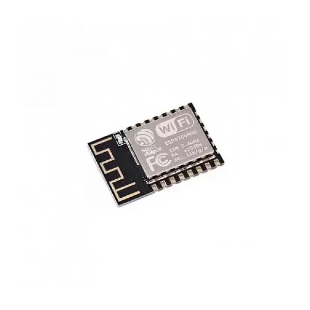
[ESP Modules] The ESP-12F ESP8266 WiFi Module is a powerful and low-cost WiFi transceiver module designed for Internet of Things (IoT) applications. Built around the ESP8266 SoC, this module integrates a full TCP/IP protocol stack, enabling microcontrollers to connect directly to WiFi networks. With its integrated 32-bit RISC processor, on-chip memory, and multiple communication interfaces, the ESP-12F module can either host an application independently or act as a WiFi adapter for another microcontroller such as Arduino, Raspberry Pi, or STM32. Each module is typically shipped with AT command firmware, allowing easy communication through UART serial interface. This means developers can quickly add WiFi functionality to existing hardware without complex programming. The ESP-12F version improves performance compared to earlier modules by offering: Stronger WiFi signal output Improved anti-interference capability Optimized PCB antenna design Better impedance matching The module supports station mode, soft-AP mode, and combined AP + station mode, making it highly versatile for IoT networking. Because of its high integration, small size, and low power consumption, the ESP-12F module is widely used in: IoT devices Home automation systems Smart appliances Wireless sensor networks Industrial monitoring systems ⭐ Key Features Based on ESP8266 SoC Built-in TCP/IP protocol stack Integrated 2.4GHz WiFi Supports Station / SoftAP / Station + AP modes Pre-programmed AT command firmware Compact SMD design Strong PCB antenna Low power consumption Multiple communication interfaces 🔧 Technical Specifications Model: ESP-12F Chipset: ESP8266 WiFi Standard: IEEE 802.11 b/g/n Frequency: 2.4 GHz Operating Voltage: 3.3V Maximum Current: ~240mA Standby Power: < 1mW Interface: UART / SPI / SDIO Baud Rate: 115200 (default) Communication Format: 8N1 Security: WPA / WPA2 Package Type: 32-Pin QFN Output Power: +19.5 dBm 📡 Supported Interfaces UART SPI SDIO 1.1 / 2.0 I2S (audio interface) Multiple GPIO pins 🎯 Applications IoT projects Smart home automation Wireless sensor networks Arduino WiFi connectivity Remote monitoring systems Industrial IoT applications 📦 Package Includes 1 × ESP-12F ESP8266 WiFi Module
 Out of stock
74HC595 Serial to Parallel Shifting IC
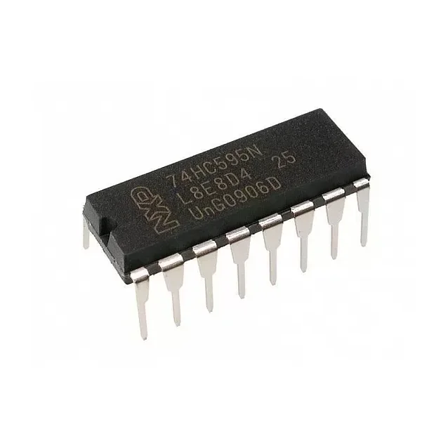
[Logic Gates IC] DESCRIPTION:- The 74HC595N is a simple 8-bit shift register IC. Simply put, this shift register is a device that allows additional inputs or outputs to be added to a microcontroller by converting data between parallel and serial formats. Your chosen microprocessor is able to communicate with The 74HC595N using serial information then gathers or outputs information in a parallel (multi-pin) format. Essentially it takes 8 bits from the serial input and then outputs them to 8 pins. This small DIP packaged IC contains an 8-bit, serial-in-parallel-out shift register that feeds an 8-bit D-type storage register with parallel 3-state outputs. Pin Configuration:- Pin Number Pin Name Description 1,2,3,4,5,6,7 Output Pins (Q1 to Q7) The 74hc595 has 8 output pins out of which 7 are these pins. They can be controlled serially 8 Ground Connected to the Ground of the circuit 9 (Q7) Serial Output This pin is used to connect more than one 74hc595 as cascading 10 (MR) Master Reset Resets all outputs as low. Must be held high for normal operation 11 (SH_CP) Clock This is the clock pin to which the clock signal has to be provided from MCU/MPU 12 (ST_CP) Latch The Latch pin is used to update the data to the output pins. It is active high 13 (OE) Output Enable The Output Enable is used to turn off the outputs. Must be held low for normal operation 14 (DS) Serial Data This is the pin to which data is sent, based on which the 8 outputs are controlled 15 (Q0) Output The first output pin. 16 Vcc This pin powers the IC, typically +5V is used. Features :- 8-bit, Serial In – Parallel out Shift register Operating Voltage: 2V to 6V Power Consumption: 80uA Output source/sink current: 35mA Output Voltage is equal to Operating voltage Minimum high-level Input Voltage: 3.15V @(Vcc=4.5V) Maximum low-level Input Voltage: 1.35V @(Vcc=4.5V) Can be easily cascaded with more IC to get more outputs Maximum Clock Frequency: 25Mhz @4.5V Available in 16-pin PDIP, GDIP, PDSO packages Where to Use 74HC595 IC:- The 74HC595 is an 8-bit Serial In – Parallel Out Shift Register, i.e. it can receive (input) data serially and control 8 output pins in parallel. This comes in very handy where do not have enough GPIO pins on our MCU/MPU to control the required number of outputs. It is often used in projects where relatively a large number of LED's has to be controlled through the Microcontroller. It can also be used to interface LCD screen since they can acts as the data bit for the LCD displays. It can also be used to control 5V loads like relays through a 3.3V microcontroller since the high-level voltage is only 3.15. So if you are looking for an IC to save on your GPIO pins on the Microcontroller then this IC might be the right choice for you. How to Use a 74HC595 IC:- The 74HC595 shift register is commonly used with microcontrollers or microprocessors to expand the GIPO functionalities. It requires only 3 pins connected to the MCU, which are Clock, Data and Latch. It has a wide operating voltage from 2V to 6V. An application circuit of the IC is shown below: Package Includes:- 1 x 74HC595 IC
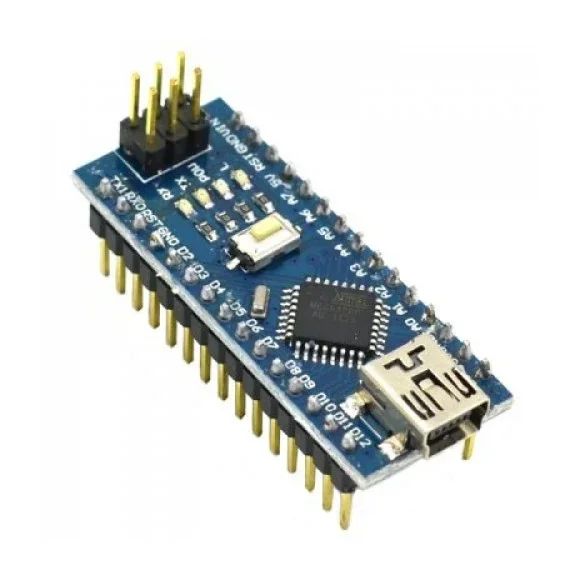
Nano CH340 Chip Board without USB cable compatible with Arduino (Soldered)
[Arduino Boards] 🔷 Nano V3 CH340 ATmega328P Development Board (Soldered Headers) Compatible with Arduino ATmega328P • CH340 USB Interface • Compact Design • Breadboard Friendly • Ready to Use The Nano V3 CH340 Development Board is a compact and powerful microcontroller board based on the ATmega328P-AU microcontroller. Fully compatible with the Arduino Nano platform, it offers the same functionality as the Arduino Uno in a much smaller, breadboard-friendly form factor, making it ideal for embedded systems, robotics, IoT, automation, and DIY electronics projects. This version features the CH340 USB-to-Serial converter, providing a cost-effective and reliable programming interface. The board comes with pre-soldered headers, allowing it to be plugged directly into a breadboard or PCB without additional soldering. Powered by the ATmega328P running at 16MHz, the Nano provides 14 digital I/O pins, 8 analog input pins, 6 PWM outputs, and supports communication protocols including UART, SPI, and I²C. The onboard bootloader allows programming directly through the Mini USB port using the Arduino IDE. The Nano can be powered through the Mini USB connector, an external 6–20V DC supply, or a regulated 5V input, with automatic power source selection for seamless operation. Note: Some computers may require the CH340 USB driver before the board is recognized. ⭐ Features Based on ATmega328P-AU microcontroller Compatible with Arduino Nano V3 CH340 USB-to-Serial interface Pre-installed Arduino bootloader Pre-soldered header pins Compact breadboard-friendly design 14 Digital I/O pins (6 PWM) 8 Analog input pins 16MHz crystal oscillator Mini USB interface for programming Automatic power source selection Manual reset button ICSP header for direct programming TX, RX, Power and L status LEDs Supports Arduino IDE 📋 Technical Specifications Product Type: Microcontroller Development Board Board Version: Nano V3 Microcontroller: ATmega328P-AU USB Interface: CH340G Operating Voltage: 5V Input Voltage (Recommended): 7V–12V DC Input Voltage Range: 6V–20V DC Digital I/O Pins: 14 PWM Channels: 6 Analog Input Pins: 8 Flash Memory: 32KB SRAM: 2KB EEPROM: 1KB Clock Speed: 16MHz USB Connector: Mini USB Communication Interfaces: UART, SPI, I²C Programming: Arduino IDE Bootloader: Pre-installed Board Dimensions: 43 × 18 mm Mounting: Breadboard Compatible 🔧 Applications Suitable for: Arduino Projects Robotics IoT Devices Home Automation Sensor Interfaces Embedded Systems Educational Projects Industrial Automation Data Logging LED Control Motor Control Smart Home Devices Wearable Electronics DIY Electronics Rapid Prototyping 📦 Package Includes 1 × Nano V3 CH340 ATmega328P Development Board (Soldered Headers) USB Cable Not Included ⚠️ Note Mini USB cable is not included. Some Windows computers may require the CH340 USB driver before programming the board. Compatible with the Arduino IDE after selecting Arduino Nano and the appropriate processor/bootloader settings. Product appearance, PCB color, and component layout may vary slightly depending on the manufacturing batch.
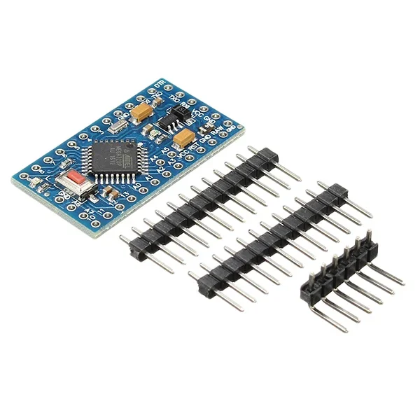
Pro Mini ATMEGA328P 3.3V/8M
[Arduino Boards] This is Pro Mini ATMEGA328P 3.3V/8MHz is a 3.3V Arduino running the 8MHz bootloader. Pro Mini ATMEGA328P come with connectors so that you can solder connector or wire with any orientation you need. It’s a great board that will get you up and running quickly. The Arduino Pro series is meant for users that understand the limitations of system voltage (3.3V), lack of connectors, and USB off board. The Pro Mini is a microcontroller board base on the ATmega328. It has 14 digital input/output pins (of which 6 can be used as PWM outputs), 6 analog inputs, an on-board resonator, a reset button, and holes for mounting pin headers. A six pin header can be connected to an FTDI cable to provide USB power and communication to the board. The Pro Mini is intended for semi-permanent installation in objects or exhibitions. The board comes with headers, allowing the use of various types of connectors or direct soldering of wires. The pin layout is compatible with the Mini Arduino. Features : 8 analog input port: A0 ~ A7. A pair of TTL level serial port transceiver : RX / TX. 6 PWM port: D3, D5, D6, D9, D10, D11. Use For Atmel Atmega328P-AU microcontroller. Support serial download. Support 9V battery. Package Includes : 1 x Pro Mini ATMEGA328P 3.3V/8M (Official Version) 3 x Male Header connector.
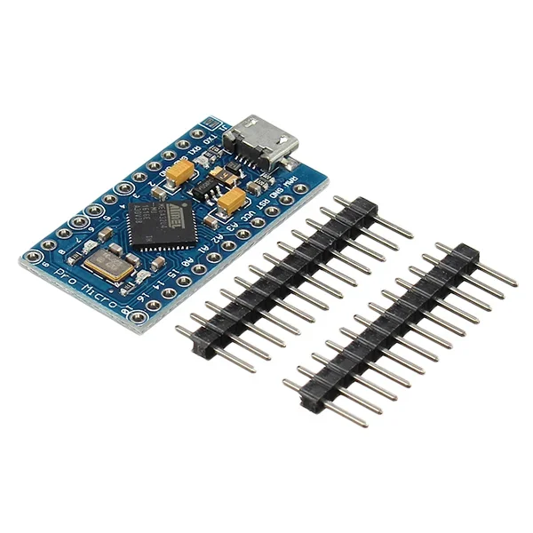 Out of stock
Pro Micro 5V 16M Mini Leonardo Microcontroller Development Board For Arduino
[Arduino Boards] This Pro Micro 5V 16M Mini Leonardo Microcontroller Development Board For Arduino development board has 4 channel 10 bit ADC, 5 PWM pins, 12 DIO, and a hardware serial connection Rx and Tx you are familiar with Running on 16MHz and 5V, this board will remind you a lot of other Arduino compatible boards that you like. There is a voltage regulator on board, so it can accept up to 12V DC. The Micro is a microcontroller board based on the ATmega32U4. It has 20 digital input/output pins (of which 7 can be used as PWM outputs and 12 as analog inputs), a 16 MHz crystal oscillator, a micro USB connection, an ICSP header, and a reset button. It contains everything needed to support the microcontroller; simply connect it to a computer with a micro USB cable to get started. It has a form factor that enables it to be easily placed on a breadboard. The Micro board is similar to the Arduino Leonardo in that the ATmega32U4 has built-in USB communication, eliminating the need for a secondary processor. This allows the Micro to appear to a connected computer as a mouse and keyboard, in addition to a virtual (CDC) serial / COM port. If you supply an unstable power supply board, be sure to connect to the “RAW”, not on the VCC pin. It has also added a PTC fuse and diode protection to the power circuit and to correct the RX and LED TX circuits. Features : ATMEGA32U4 running in 5V / 16MHz Support Arduino IDE V1.0.1 Micro USB interface programming on the board Four 10-bit ADC pin 12 digital I / O (5 PWM capability) Rx and Tx hardware serial connection. Pin Diagram: Package Includes : 1 x Pro Micro 5V 16M Mini Leonardo Microcontroller Development Board For Arduino
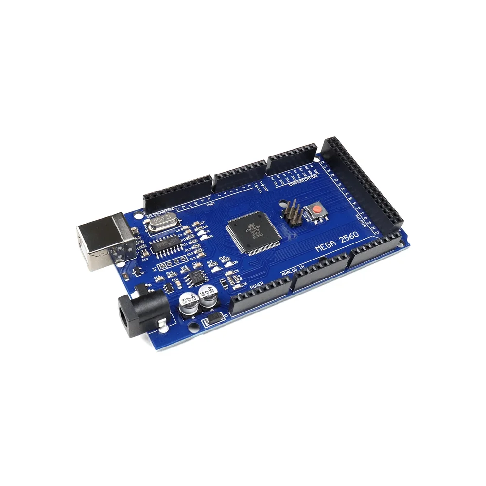 Out of stock
ATmel MCU ATMEGA16U2 MEGA 2560 R3 Improved Version CH340G Board
[Arduino Boards] The ATmel MCU ATMEGA16U2 MEGA 2560 R3 Improved Version CH340G Board is a micro-controller board base on the ATmega2560. It has a USB host interface to connect with Android based phones, base on the MAX3421e IC. It has 54 digital input/output pins (of which 15 can be used as PWM outputs); 16 analog inputs, 4 UARTs (hardware serial ports), a 16 MHz crystal oscillator; a USB connection, a power jack, an ICSP header, and a reset button. The MEGA ADK is base on the Mega 2560. Similar to the Mega 2560 and Uno, it features an ATmega8U2 program as a USB-to-serial converter. Revision 3 of the Mega ADK board has a resistor pulling the 8U2 HWB line to ground, making it easier to put into DFU(Device Firmware Upgrade) mode. The board has the following new features: 1.0 pin-out: added SDA and SCL pins that are near to the AREF pin and two other new pins placed near to the RESET pin, the IOREF that allow the shields to adapt to the voltage provided from the board. In the future, shields will be compatible both with the board that uses the AVR, which operate with 5V and with the Arduino Due which operates with 3.3V. The second one is a not connected pin, that is reserved for future purposes. Stronger RESET circuit. The Mega Arduino R3 Android Accessory Development Kit (ADK) can be powered via a USB connection or with an external power supply. The power source is selected automatically. External (non-USB) power can come either from an AC-to-DC adapter (wall-wart) or battery. The adapter can be connected by plugging a 2.1mm centre-positive plug into the board’s power jack. Leads from a battery can be inserted in the GND and Vin pin headers of the POWER connector. Because the Mega R3 Android Accessory Development Kit (ADK) is a USB Host, the phone will attempt to draw power from it when it needs to charge. When the ADK is powered over USB, 500mA total is available for the phone and board. Package Includes : 1 x Mega R3 Android Accessory Development Kit (ADK) board.
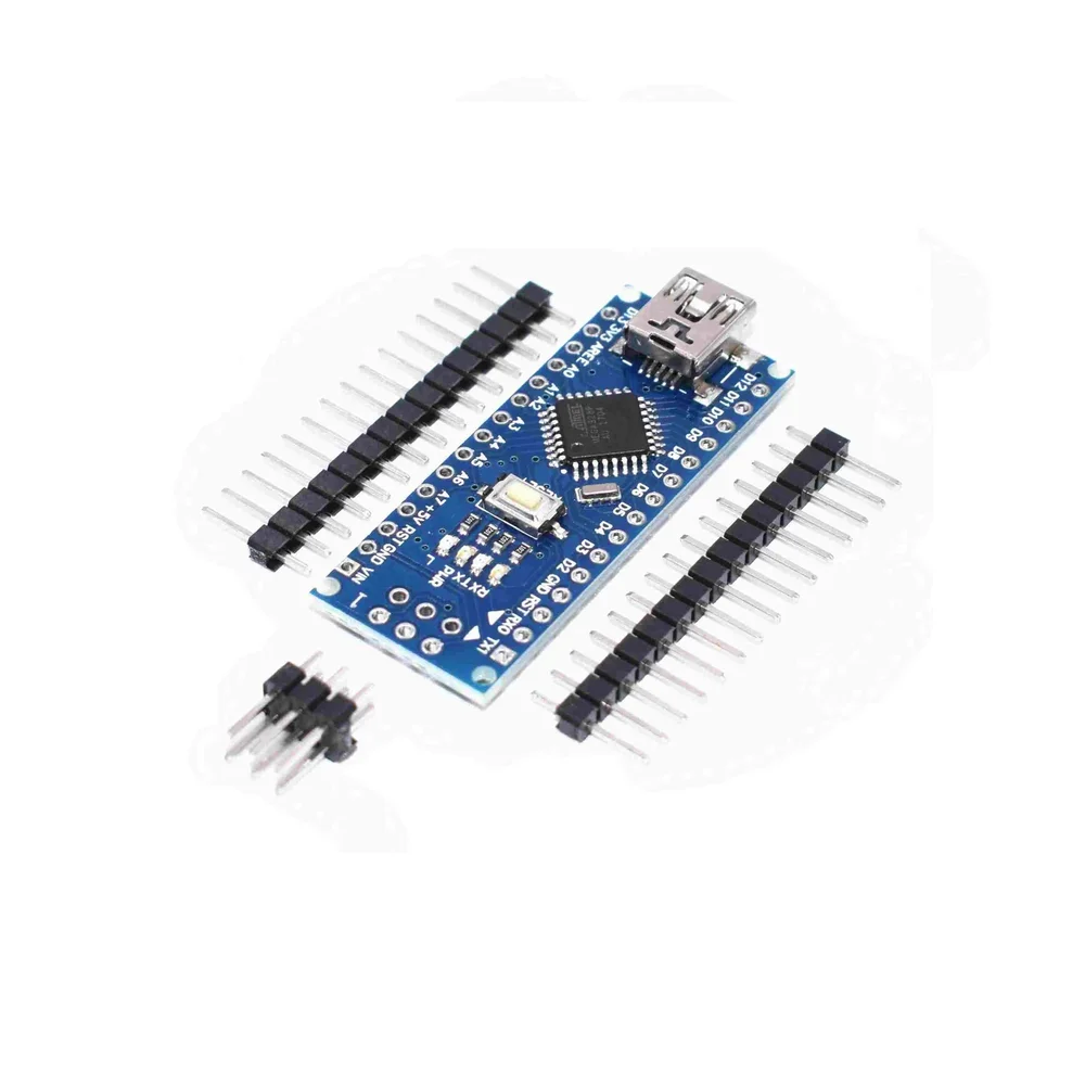
Nano Board R3 with CH340 chip without USB Cable compatible with Arduino (Unsoldered)
[Arduino Boards] The Nano Board R3 with CH340 chip without USB Cable chipboard is based on the famous Arduino platform and does all the functions of Uno, but with a smaller footprint. The Nano Board R3 with CH340 chip without USB Cable is vital for your small project where you don’t need much of a pin-outs but the small size is very important to make it look good. This Nano equips a low-cost USB-Serial Chip that makes it less in price than Nano with FTDI USB-Serial Chip used on older versions of Arduino Nano. The Nano Arduino is a small, complete, and breadboard-friendly board based on the ATmega328 (Nano R3). It has more or less the same functionality of the Uno but in a different package. It lacks only a DC power jack and works with a Mini-B USB cable instead of a standard one. The Nano can be power via the mini-USB connection, 6-20V unregulated external power supply (pin 30), or 5V regulated external power supply (pin 27). The power source is automatically selected to the highest voltage source. The size of Nano V3.0 with CH340 Chip is only 43 mm x 18 mm; it comes with 6 PWM I/O from the total of 14 digitals I/O, 8 analog inputs, 16Mhz clock speed and 32kB of flash memory. Note:- CH340 chip might not work directly with some PC/Laptop, you will need some ch340 drivers. This board comes with OLD BOOTLOADER buy it accordingly Features : 1 pair of TTL level serial transceiver ports RX / TX Using Atmel Atmega328P-AU MCU There is a bootloader installed in it Support USB download and Power Support for external 5V ~ 12V DC power supply It Supports power supply by 9V battery Support ISP download Automatic reset during program download. Power OK blue LED on the bottom. Green (TX), red (RX) and orange (L) LED. +5V to AREF jumper. Auto-sensing/switching power input. Small mini-B USB for programming and serial monitor. ICSP header for direct program download. Standard 0.1” spacing DIP (breadboard friendly). Manual reset switch. Package Includes : 1 x Nano Board R3 with CH340 chip without USB Cable compatible with Arduino (Unsoldered)
 Out of stock
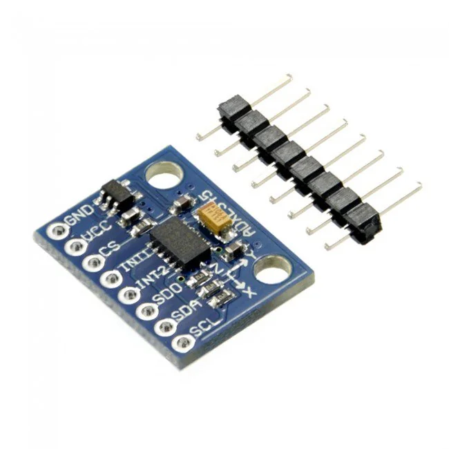
ADXL345 Tripple Axis Accelerometer Board
[Accelerometer and Gyro Sensor] ADXL345 Tripple Axis Accelerometer Board is a small, thin, low-power, 3-axis accelerometer with a high resolution (13-bit) measurement at up to ±16g. Digital output data is format as a 16-bit two’s complement and is accessible through either an SPI (3- or 4-wire) or I2C digital interface. The ADXL345 Tripple Axis Accelerometer Board is well suited for mobile device applications. It measures the static acceleration of gravity in tilt-sensing applications, as well as dynamic acceleration resulting from motion or shock. Its high resolution (4 mg/LSB) enables measurement of inclination changes less than 1.0°. Several special sensing functions are provided. Activity and inactivity sensing detect the presence or lack of motion and if the acceleration on any axis exceeds a user-set level. Tap sensing detects single and double taps. Free-fall sensing detects if the device is falling. These functions can be mapped to one of two interrupt output pins. An integrated, patent-pending 32-level first-in, first-out (FIFO) buffer can be used to store data to minimize host processor intervention. Low power modes enable intelligent motion-based power management with threshold sensing and active acceleration measurement at extremely low power dissipation. Applications : Pointing devices. Handsets. Medical Instrumentation. Gaming. Industrial instrumentation. Personal navigation devices. Hard disk drive (HDD) protection. Fitness equipment. defense and aerospace. Note: This package does not include the Arduino board, you have to buy it separately. Features : Ultra-Low Power: 40µA in measurement mode, 0.1µA in standby@ 2.5V. Free-Fall Detection. Tap/Double Tap Detection. Flexible interrupt modes mappable to either interrupt pin Measurement ranges selectable via serial command Bandwidth selectable via serial command Wide temperature range (−40°C to +85°C). 10,000 g shock survival. Support 5V/3.3V voltage input, onboard RT9161 power chip, lower pressure drop faster than 1117, the faster load speed of response, very suitable for high-noise power supply environment. User-selectable resolution Fixed 10-bit resolution. Full resolution, where resolution increases with G range, up to 13-bit resolution at ±16 g (maintaining 4 mg/LSB scale factor in all G ranges). Package Includes : 1 x ADXL345 Tripple Axis Accelerometer Board.
 Out of stock
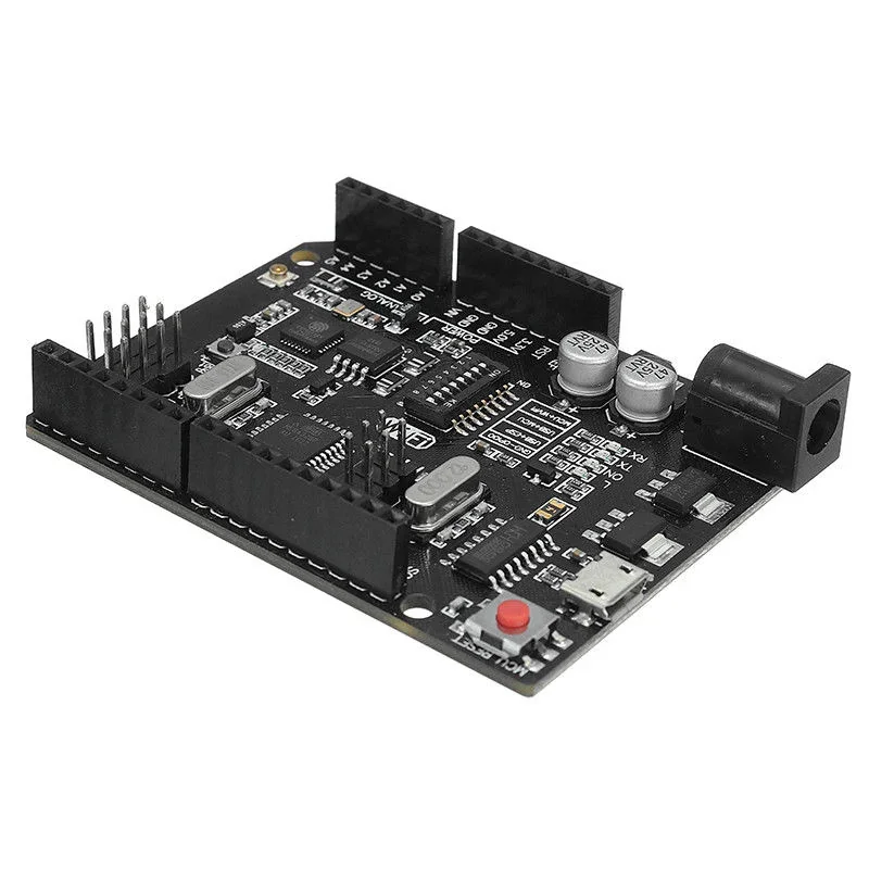
Uno+WiFi R3 AtMega328p+NodeMSU ESP8266 Compatible for Arduino UNO
[Arduino Boards] Arduino UNO WIFI ESP8266 CH340 Development Board Uno+WiFi R3 AtMega328p+NodeMSU ESP8266 8MB Memory USB-TTL CH340G Compatible for Arduino UNO is full integration on one board: Uno R3 ATmega 328 and WiFi ESP8266 with memory 8Mb (MegaByte). All of the modules can work together or separately. And everyone has their own pinout headers. The convenient solution for the development of new projects requiring Uno and WiFi. Via USB you can update sketches and firmware for ATmega328 and for ESP8266. For this onboard have the USB-serial converter CH340G. It is a modernized version of the classic Arduino UNO R3 board. Full integration of a microcontroller ATmega328 and a Wi-Fi chip ESP8266 with 8 MB memory on one board. All modules can work together or individually. Each of the microcontrollers has led to connecting peripheral sensors and modules. A convenient solution for developing new projects that require Wi-Fi. Through USB, you can update sketches and firmware for both ATmega328 and ESP8266. For this on board, there is a UART converter CH340G. The board has a DIP switch, which switches the modes of interaction of microcontrollers ATmegaa328 and esp8266. The operations of this board are very simple. The board has a DIP switch, to connect the modules. For example, USB and ATmega328, USB and ESP8266, ATmega328 and ESP8266. Table DIP- switch: Connection DIP 1 2 3 4 5 6 7 ATmega328<->ESP8266 ON ON OFF OFF OFF OFF OFF USB <->ATmega328 OFF OFF ON ON OFF OFF OFF USB<->ESP8266 (Update firmware or sketch) OFF OFF OFF OFF ON ON ON USB<->ESP8266 (communication) OFF OFF OFF OFF ON ON OFF All independent OFF OFF OFF OFF OFF OFF OFF Features: USB-TTL converter. USB5V (500mA max.)Power IN. Logic Level: 5V. Operating Supply Voltage: 5V. Digital I/O Pins: 14. Analog I/O Pins: 6. Interface Type: serial. Operating temperature: −40С°/+125С°. Specifications: Microcontroller ATmega328IC Wi-Fi Module ESP8266 Input supply voltage (V) 3.3 ~ 5 Current consumption (mA) 800 USB to serial converter CH340G VIN/DC Jack (V) 9 ~ 24 WiFi 802.11 b/g/n 2.4 GHz USB type Micro USB USB Clock Frequency (MHz) 16 Memory Size (MB) 8 Package Includes: 1 x Uno+WiFi R3 AtMega328p+NodeMSU ESP8266 Compatible for Arduino UNO