
All products · 11 of 1440
Electronics, sensors, robotics kits, PC components, peripherals — everything Unik Systems carries, in one place.
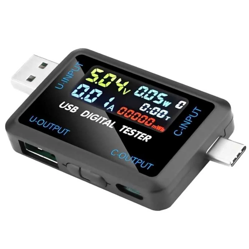
10-in-1 USB & Type-C Digital Tester – IPS Voltmeter, Ammeter, Impedance & Capacity Meter
[Ammeter and Voltmeter] The 10-in-1 USB & Type-C Digital Power Tester is a multifunction USB measurement instrument developed for engineers, technicians, hobbyists, and electronics enthusiasts. It accurately monitors USB charging performance while providing comprehensive electrical measurements for USB-A and USB Type-C devices. Equipped with a bright IPS true-color LCD display, the tester simultaneously displays ten important charging parameters including Voltage, Current, Power, Capacity (mAh), Energy (mWh), Cable Resistance, Temperature, Charging Time, D+ Voltage, and D− Voltage. The tester features both USB-A and USB Type-C input/output interfaces, allowing compatibility with traditional USB chargers as well as modern USB-C Power Delivery devices. It supports testing of fast chargers, mobile phones, tablets, laptops, power banks, USB cables, and various USB-powered electronics. With support for measurements up to 150W and 5A, this tester is suitable for high-power USB-C PD chargers while consuming less than 20mA of operating current. Built-in control buttons allow users to switch display modes, perform fast-charge diagnostics, and manage measurement functions easily. Its compact design makes it an excellent tool for electronics repair, charger verification, cable testing, battery capacity measurement, laboratory work, and DIY electronics projects. 🔹 Key Features Dual Interface: USB-A & USB Type-C Input/Output Supports USB PD and Fast Charging IPS Full Color LCD Display Measures Voltage, Current and Power Capacity (mAh) & Energy (mWh) Measurement Cable Resistance (Impedance) Measurement Internal Temperature Monitoring USB D+ / D− Voltage Detection Charging Timer Function High Accuracy Measurement Low Self Power Consumption Compact Portable Design Easy Operation with Dedicated Function Buttons 🔹 Technical Specifications Product Type: USB Digital Power Tester Display: IPS True Color LCD Input Interface: USB-A / USB Type-C Output Interface: USB-A / USB Type-C Maximum Power Measurement: 150W Maximum Current: 5A Voltage Measurement: USB Standard & USB-C PD Power Measurement Range: 0–150W Current Measurement: Up to 5A Capacity Measurement: mAh Energy Measurement: mWh Impedance Measurement Range: 1–999.9Ω Temperature Measurement: 0°C to 80°C USB D+ Voltage Range: 0–2.99V USB D− Voltage Range: 0–2.99V Timer Range: 999 Hours 59 Minutes Refresh Rate: Approximately 500ms Self Power Consumption: <20mA Operating Buttons: Mode / Power Dimensions: 76.9 × 38 × 11 mm 🔹 Applications This USB tester is suitable for: USB charger testing USB-C PD charger testing Power bank capacity testing Mobile charger verification Fast charging protocol diagnostics USB cable resistance testing Laptop USB-C charger testing Electronics repair DIY electronics projects Laboratory measurements Battery charging analysis Quality inspection of USB power supplies 🔹 Package Includes 1 × 10-in-1 USB & Type-C Digital Power Tester 🔹 Frequently Asked Questions (FAQ) What does "10-in-1" mean? It measures ten important parameters: Voltage, Current, Power, Capacity, Energy, Impedance, Temperature, Charging Time, D+ Voltage, and D− Voltage. Does it support both USB-A and USB Type-C? Yes. It features both USB-A and USB Type-C input and output interfaces. What is the maximum power it can measure? Up to 150W. What is the maximum current supported? Up to 5A. Can it test USB-C laptop chargers? Yes. It supports high-power USB-C PD chargers up to 150W. Can it measure charging cable quality? Yes. It measures cable impedance from 1Ω to 999.9Ω. Does it display temperature? Yes. It includes an internal temperature sensor with a range of 0°C to 80°C. Does it require batteries? No. It is powered directly from the connected USB source. Can it measure power bank capacity? Yes. It records charging capacity in mAh and mWh. Does it support fast charging protocols? Yes. It can monitor USB D+ and D− voltages, helping identify fast charging protocol handshakes.
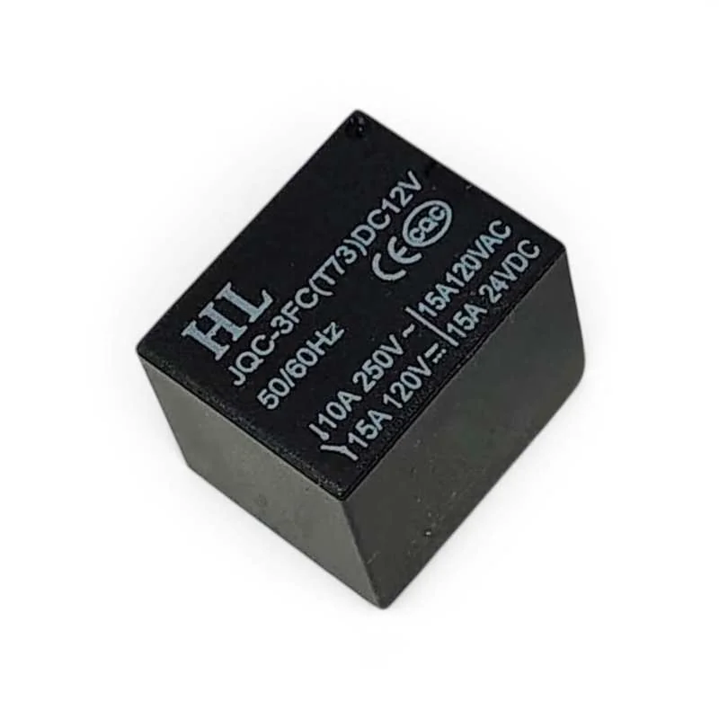
5 Pin Mini SPDT Relay 12V 10A 250V PCB Mount Electromagnetic Relay
[Relay Module, Relays] 12V PCB Mount Sugar Cube SPDT Relay – 5 Pin 10A The 12V PCB Mount Sugar Cube SPDT Relay is a compact Single Pole Double Throw (SPDT) electromagnetic relay designed for switching AC and DC electrical loads using a microcontroller, sensor, automation circuit, or other low-power control system. Its compact PCB-mount design makes it suitable for DIY electronics, home automation, security systems, switching circuits, motor control, lighting control, and embedded applications. The relay features a 12V DC coil and a 5-pin SPDT configuration consisting of two coil terminals, COM (Common), NO (Normally Open), and NC (Normally Closed) contacts. When the coil is energized, the internal contact switches between the NC and NO terminals. With contact ratings of up to 10A at 250V AC, 10A at 125V AC, 12A at 120V DC, and 10A at 28V DC, this relay is suitable for a wide range of electrical switching applications. ⭐ Key Features SPDT (Single Pole Double Throw) relay 12V DC coil Compact Sugar Cube design 5-pin configuration PCB mounting type 10A @ 250V AC contact rating 10A @ 125V AC contact rating 12A @ 120V DC contact rating 10A @ 28V DC contact rating Coil resistance: approximately 270Ω Approximately 45mA nominal coil current 50/60Hz frequency specification Fast switching response Suitable for microcontroller and sensor-controlled switching Ideal for automation and control applications 📋 Technical Specifications Product Type: PCB Mount Relay Relay Type: SPDT (Single Pole Double Throw) Contact Configuration: 1 Form C Number of Pins: 5 Coil Voltage: 12V DC Trigger Voltage: 12V DC Coil Resistance: 270Ω Nominal Coil Current: Approximately 45mA Frequency: 50/60Hz Maximum AC Load: 10A @ 250V AC Maximum AC Load: 10A @ 125V AC Maximum DC Load: 12A @ 120V DC Maximum DC Load: 10A @ 28V DC Operating Time: 10ms Release Time: 5ms Mounting Type: PCB Mount Contact Terminals: COM / NO / NC Coil Terminals: Coil End 1 / Coil End 2 🔌 Pin Configuration Coil End 1: One terminal of the 12V DC relay coil Coil End 2: Other terminal of the 12V DC relay coil COM: Common switching contact NO: Normally Open contact NC: Normally Closed contact When the relay coil is not energized, COM is connected to NC. When the 12V DC coil is energized, COM switches from NC to NO. 🛠️ How It Works The relay uses an electromagnetic coil to mechanically switch an electrical circuit. Applying 12V DC to the coil energizes the relay and changes the contact position. A load connected between COM and NC remains connected when the relay is inactive. A load connected between COM and NO remains disconnected until the relay coil is energized. This allows a low-power control circuit such as an Arduino, microcontroller, sensor, timer, or automation controller to control a higher-current AC or DC load. 🔧 Applications Arduino Projects Microcontroller Projects Sensor-Controlled Switching Home Automation Security Systems Lighting Control Fan Control Motor Control Pump Control Power Supply Switching Industrial Control Systems Embedded Electronics DIY Electronics Projects 📦 Package Includes 1 × 12V PCB Mount Sugar Cube SPDT Relay – 5 Pin 10A ⚠️ Precautions Use a suitable 12V DC supply for the relay coil. Do not exceed the specified contact voltage and current ratings. Check the COM, NO, NC, and coil terminals before wiring. Use suitable flyback protection when driving the relay coil from sensitive electronic circuits. Use appropriate suppression/protection components for inductive loads such as motors, solenoids, and coils. Provide sufficient PCB insulation and clearance when switching mains voltage. Disconnect power before changing or modifying wiring. Do not touch exposed mains-voltage terminals during operation.
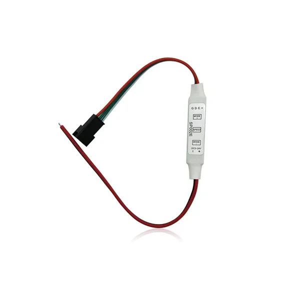
SP002E DC5-24V led pixel controller 3 keys LED light strips
[RGB LED CONTROLLER] SP002E DC5-24V led pixel controller 3 keys LED light strips (27cm) Product Description SP002E DC5-24V led pixel controller 3 keys (27cm) The SP002E LED pixel controller has a three key layout with easy-to-use function keys. It has a range of features such as brightness adjustment, auto shut-off and power-saving mode. It can be set to run at 4 different modes and controlled with 3 buttons. It has 3 modes of operation, which are static, strobe, and a timer. This controller can operate from 5 volts to 24 volts DC supply. Features Easy to connect Flexible key operating system Multi-functioning controller for better performance
 Out of stock
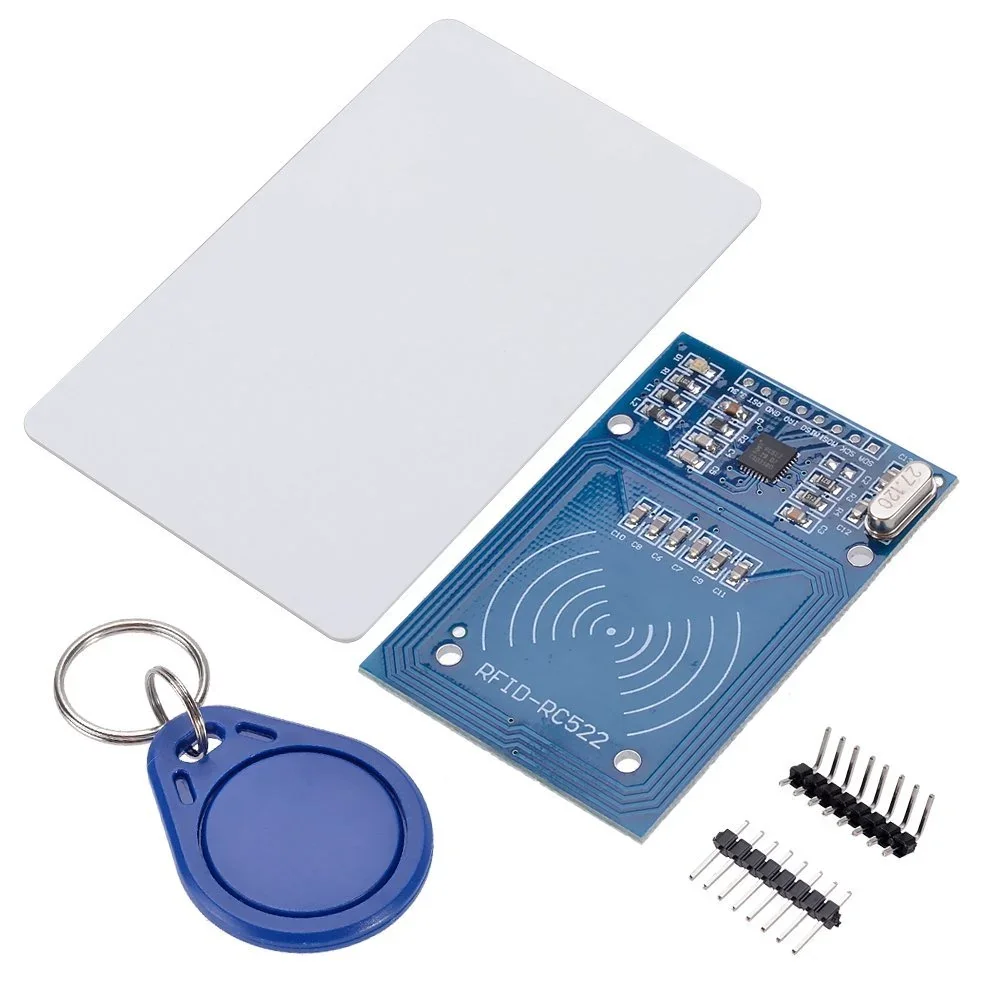
RFID Reader/Writer RC522 SPI S50 with RFID Card and Tag
[IR and PIR Sensors] Do you want to know the work of RFID Reader/Writer RC522 SPI S50 CARD AND KEYCHAIN, then this Product is best for you . With this Product, you can detect radio waves produced by a reader to detect the presence of (then read the data stored on) an RFID tag This is RFID Reader/Writer RC522 SPI S50 CARD AND KEYCHAIN which works on non-contact 13.56mhz communication, is designed by NXP as low power consumption, low cost, and compact size read and write chip, is the best choice in the development of smart meters and portable hand-held devices. It uses an advanced modulation system, fully integrated at 13.56MHz with all kinds of positive non-contact communication protocols. Support 14443A compatible answer signal. DSP deals with ISO14443A frames and error correction. This module can fit directly in handheld devices for mass production. The module uses the 3.3V power supply and can communicate directly with any CPU board by connecting through the SPI protocol, which ensures reliable work, good reading distance. Features : Highly integrated analog circuitry to demodulate and decode responses. Supports ISO/IEC 14443 A/MIFARE. Typical operating distance in reading/Write mode up to 50 mm. Supports ISO/IEC 14443 A higher transfer speed communication up to 848 kBd. SPI up to 10 Mbit/s. FIFO buffer handles 64 bytes send and receive. Flexible interrupt modes. Power-down by software mode. Programmable Timer. 2.5 V to 3.3 V power supply. CRC coprocessor. Internal self-test. Package Includes 1 x RFID-RC522 Reader/Write Module 1 x Standard blank RFID card 2 x A Straight & right-angle header strip 1 x Special-shaped keychain RFID tag
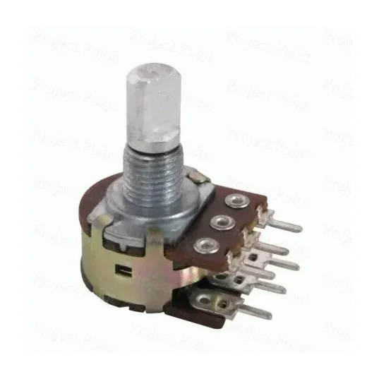
10K Ohm 16mm Linear Taper 6-Pin Dual Gang Rotary Potentiometer
[Potentiometer] 16mm 10KΩ 6-Pin Dual-Gang Rotary Potentiometer The 16mm 10KΩ 6-Pin Rotary Potentiometer is a compact and versatile dual-gang rotary potentiometer designed to control two separate electrical channels simultaneously using a single rotary shaft. With 6 pins in total, each potentiometer section has 3 terminals, making it suitable for stereo audio control, dual-channel signal adjustment, amplifier circuits, tone control, and various DIY electronics applications. By rotating the shaft, the resistance of each potentiometer section can be adjusted smoothly. The dual-gang construction allows both channels to be controlled together, making this potentiometer particularly useful for stereo volume control and other applications requiring synchronized adjustment. ⭐ Key Features 10KΩ resistance value 16mm body diameter 6-pin dual-gang configuration 3 pins per potentiometer section Single rotary shaft controls both gangs Smooth and reliable rotary operation Compact design Suitable for PCB and panel mounting Ideal for stereo and dual-channel applications Suitable for audio and general electronic circuits Compatible with suitable potentiometer knobs 📋 Technical Specifications Product Type: Rotary Potentiometer Resistance Value: 10KΩ Body Diameter: 16mm Configuration: Dual Gang Number of Pins: 6 Pins per Gang: 3 Operation: Single Turn Rotary Shaft Length: 9mm Total Potentiometer Height: 27mm Mounting Type: PCB / Panel Mount Application: Variable Resistance / Voltage Control 🔌 Pin Configuration The potentiometer has 6 pins in total, divided into two independent 3-pin sections: Pins 1, 2 & 3: First potentiometer section Pins 4, 5 & 6: Second potentiometer section Each section consists of two resistive-track terminals and one center wiper terminal. Rotating the shaft moves the wiper and changes the resistance or output voltage. 🔧 Applications Stereo Audio Volume Control Audio Amplifiers Tone Control Circuits Pre-Amplifier Circuits Dual-Channel Signal Adjustment LED Brightness Control Motor Speed Control Power Supply Adjustment 555 Timer Circuits Arduino Projects ESP32 Projects DIY Electronics Projects Audio Equipment Electronic Prototyping 🛠️ How to Use The two outer terminals of each potentiometer section can be connected across the required voltage or signal path, while the center terminal works as the adjustable wiper output. In stereo audio applications, one gang can be used for the left channel and the other gang for the right channel, allowing both channels to be adjusted simultaneously. 📦 Package Includes 1 × 16mm 10KΩ 6-Pin Dual-Gang Rotary Potentiometer ⚠️ Precautions Check the pin configuration before connecting the potentiometer. Do not exceed the electrical limits of the connected circuit. Ensure correct wiring when using both gangs for stereo applications. Use a suitable knob compatible with the shaft. The exact taper and shaft shape may vary depending on the product variant.
 Out of stock
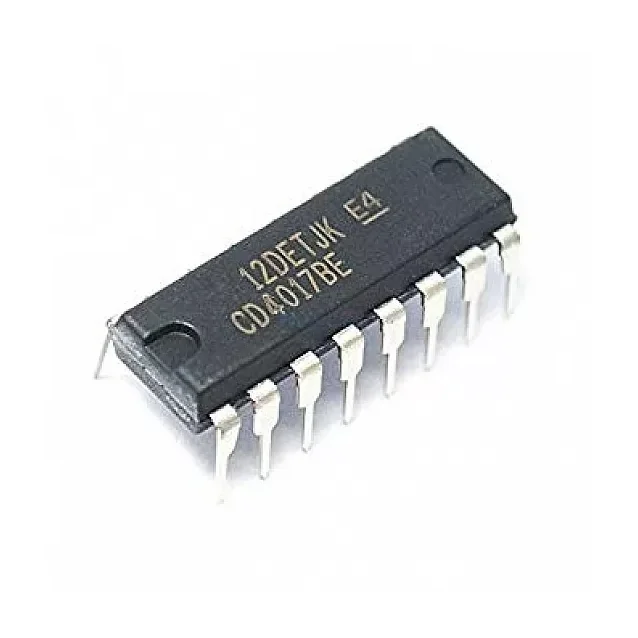
4017 Decade Counter IC
[Timer,Clock,Counter ICs] DESCRIPTION:- This IC 4017 is a 16-pin counter IC. It is a CMOS decade counter cum decoder circuit. It can count from zero to ten and its outputs are decoded. This saves a lot of board space and time required to build our circuits when our application demands using a counter followed by a decoder IC. IC 4017 is a digital counter plus decoder circuit. CD4017 Pin Configuration :- Pin Number Pin Name Description 1 to 7 and 9,10,11 Output pins Q0 to Q9 These are the 10 output pins on which the counting occurs, they are not in order hence verify pin diagram above 8 Vss or Ground Connected to the Ground of the circuit 12 Carry Out (CO) This pin goes high after the IC counts from 1 to 10. This is used as carry while counting. 13 Clock Enable (EN) This is an input which when made high will hold the count at the current state 14 Clock The counting happens when this clock pulse goes high , this pin is normally connected to 555 timer or other uC to produce a pulse 15 Resets As the name suggests this pin resets the count back to 1 16 Vdd / Vcc Connects to the supply voltage typically +5V Features:- High speed 16 pin CMOS Decade counter Supports 10 decoded outputs Wide supply voltage range from 3V to 15V, typically +5V TTL compatible Maximum Clock Frequency: 5.5Mhz Available in 16-pin PDIP, GDIP, PDSO packages Where to use CD4017 IC:- The IC CD4017 is used for counting applications, it has the capability to turn on 10 outputs sequentially in a pre-defined time and reset the count or hold it when required. It also has the capability to indicate the status of counting using Carry pin. This is commonly used for Led chasers and other logical output projects, so if you are looking for a sequential decoded counting IC that can count up to 10 then this IC will be your right choice How to use a CD4017 IC:- The IC can work from 3V to 15V, but normally powered with +5V to the Vdd/Vcc pin and the Ground/Vss pin is connected to ground. We have 10 output pins ranging from Q0 to Q9, these pins can be connected to any load but we are using LEDs here as shown in the circuit below. Package Includes :- 1 X 4017 Decade Counter IC
 Out of stock
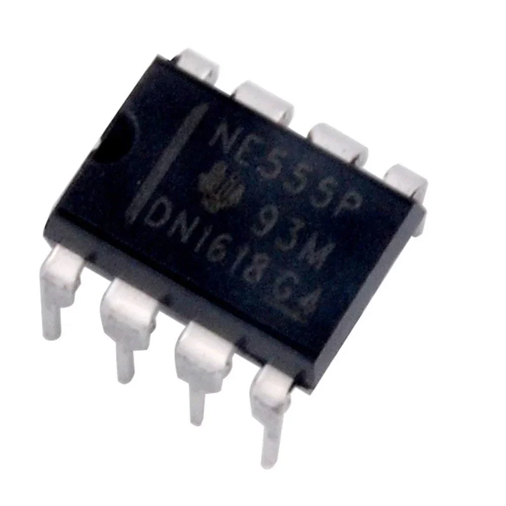
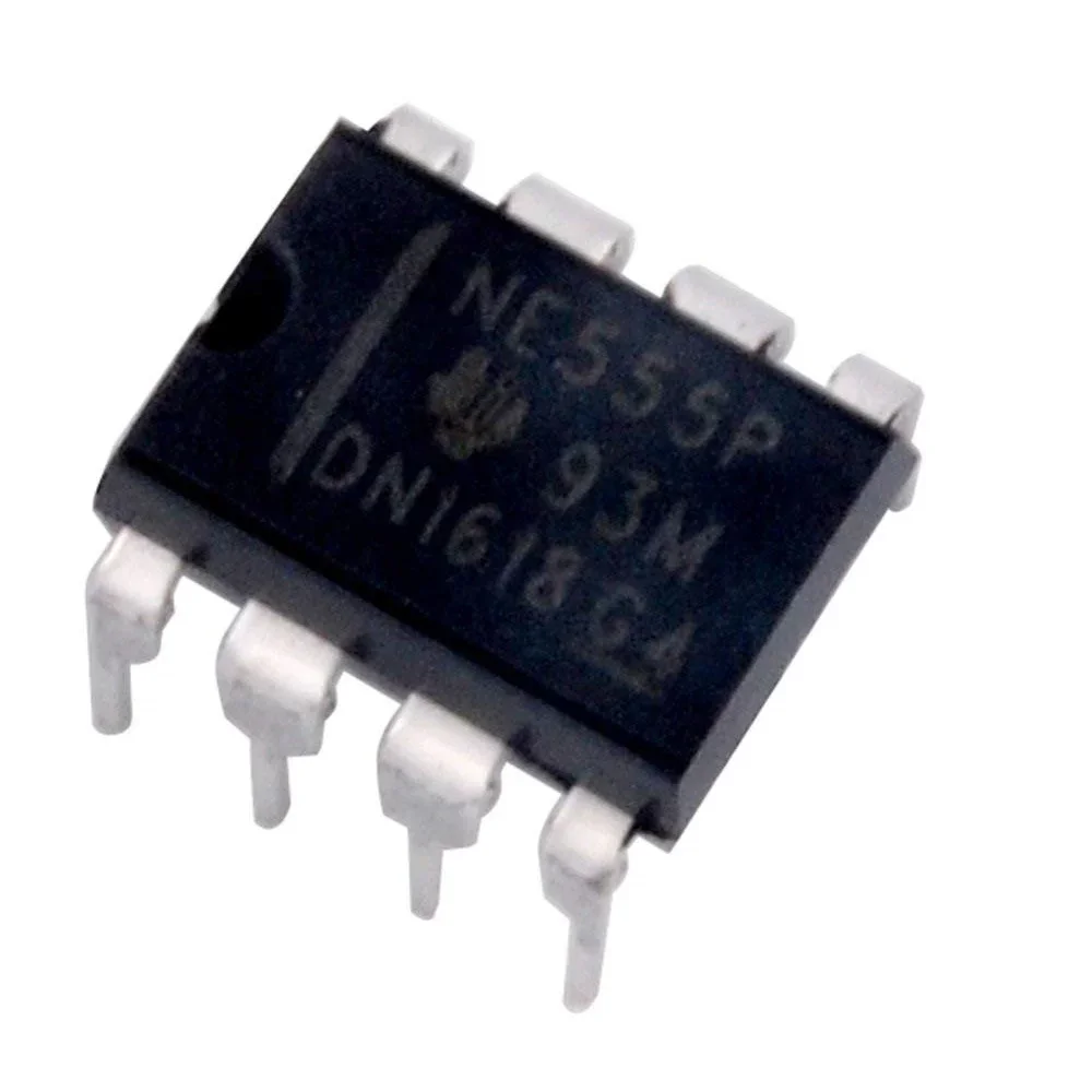
NE 555 P PDIP-8 Timer IC
[Timer,Clock,Counter ICs] The NE 555 P timer IC is a precision timing circuit capable of producing accurate time delays or oscillation. In the time-delay or monostable mode of operation, the timed interval is controlled by a single external resistor and capacitor network. In the as table mode of operation, the frequency and duty cycle can be controlled independently with two external resistors and a single external capacitor. The threshold and trigger levels normally are two-thirds and one-third, respectively, of VCC. These levels can be altered by the use of the control voltage terminal. When the trigger input falls below the trigger level, the flip-flop is set, and the output goes high. If the trigger input is above the trigger level and the threshold input is above the threshold level, the flip-flop is reset and the output is low. Features: Timing from microseconds to hours A stable or monostable operation Adjustable duty cycle TTL compatible output can sink or source up to 200mA Applications: Clock & Timing, Consumer Electronics, Aerospace, Defence, Military, Embedded Design & Development Package Includes: 1 x NE 555 P PDIP-8 Timer IC
 Out of stock
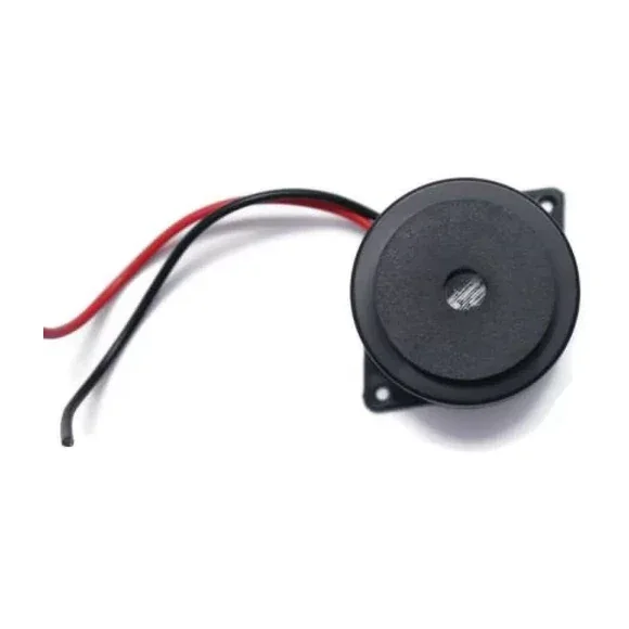
Piezo Electric Active Big Buzzer B27
[Buzzer And Mic] 5-24V Buzzer Continues Beep – Big 27 A buzzer or beeper is an audio signaling device, which may be mechanical, electromechanical, or piezoelectric (piezo for short). Typical uses of buzzers and beepers include alarm devices, timers, and confirmation of user input such as a mouse click or keystroke. A piezoelectric element may be driven by an oscillating electronic circuit or other audio signal sources, driven with a piezoelectric audio amplifier. Sounds commonly used to indicate that a button has been pressed are a click, a ring, or a beep. Voltage: 5 V Sound : 90dB Housing Material: ABS Plastic. Perfect for motorcycle stand alarm, alarm clock, or any project which you need an alarm buzzer for getting immediate attention. Note: This product comes in different design patterns. We ship randomly.
 Out of stock
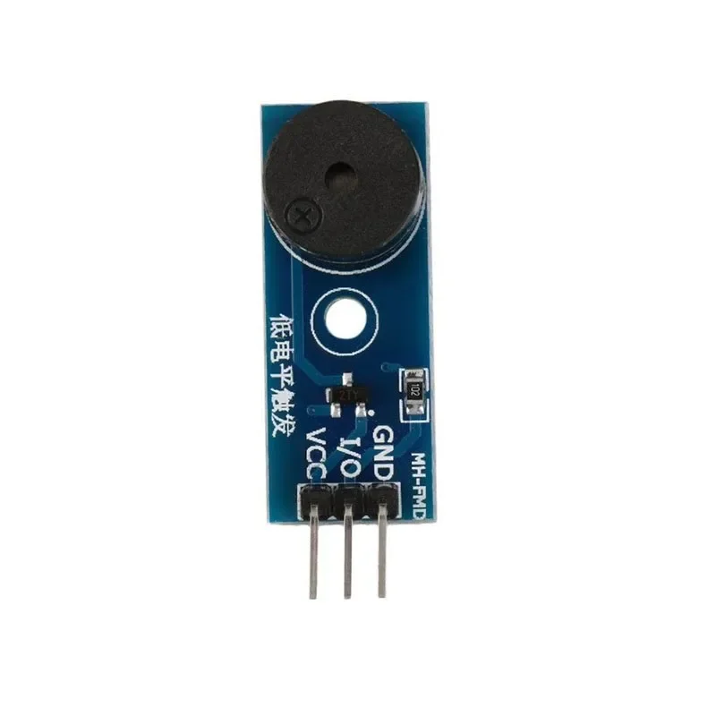
High Current Active Alarm Buzzer Driver Module
[Current Sensor] A High Current Active Alarm Buzzer Driver Module is an audio signaling device, which may be mechanical, electromechanical, or piezoelectric. Just like what you are viewing now, it is 5V DC Electronic Part Active Buzzer Module. Using top quality material, it is durable in use. What’s more? This active buzzer rings out as long as it is electrified. Compared with a passive buzzer, it is a bit expensive but easier to control. Typical uses of buzzers include alarm devices, timers, and confirmation of user input such as a mouse click or keystroke. A good choice for you all! Features: An active buzzer with a concussion internal source- so long as it will be called an energized. The program easy to control- SCM can let a high-low sound- while passive buzzer did not. Operating voltage 3.3V-5V PCB Dimension: 3.1cm*1.3cm. Color: Blue Easy to use Package Includes : 1 x High Current Active Alarm Buzzer Driver Module
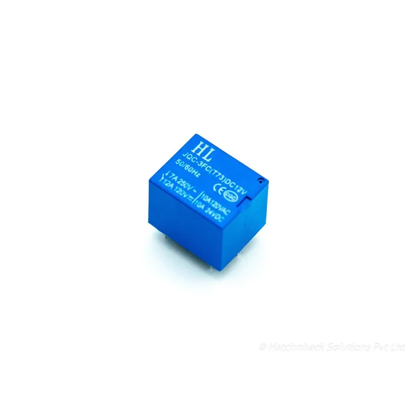
12V PCB Mount Sugar Cube SPDT Relay – 5 Pin 7A
[Relays] 12V PCB Mount Sugar Cube SPDT Relay – 5 Pin 7A The 12V PCB Mount Sugar Cube SPDT Relay is a compact Single Pole Double Throw (SPDT) electromagnetic relay designed for switching AC or DC loads using a microcontroller, sensor, control circuit, or other low-power trigger source. Despite its small size, this relay can be used to control loads up to 7A at 250V AC according to the provided specifications. The relay operates with a 12V DC coil and has a coil resistance of approximately 270Ω, with a nominal coil current of around 45mA. Its compact PCB-mount design makes it suitable for use in automation systems, switching circuits, security systems, control panels, DIY electronics, and embedded projects. The relay features 5 pins: two coil terminals, COM (Common), NO (Normally Open), and NC (Normally Closed). The COM terminal is switched between NO and NC when the relay coil is energized or de-energized. ⭐ Key Features SPDT (Single Pole Double Throw) relay 12V DC coil Compact Sugar Cube design PCB mounting type 5-pin configuration Coil resistance: approximately 270Ω Nominal coil current: approximately 45mA Suitable for switching AC and DC loads Maximum AC load: 7A @ 250/125V AC Compact and easy to install Suitable for microcontroller and sensor-controlled switching Useful for automation and control applications 📋 Technical Specifications Product Type: PCB Mount Relay Relay Type: SPDT Contact Configuration: 1 Form C Number of Pins: 5 Coil Voltage: 12V DC Trigger Voltage: 12V DC Coil Resistance: 270Ω Trigger / Nominal Coil Current: Approximately 45mA Maximum AC Load Current: 7A @ 250/125V AC Maximum DC Load Current: 10A @ 24/120V DC as specified Operating Time: 10ms Release Time: 5ms Mounting Type: PCB Mount Contact Terminals: COM / NO / NC Coil Terminals: Coil End 1 / Coil End 2 🔌 Pin Configuration Coil End 1: One terminal of the 12V DC relay coil Coil End 2: Other terminal of the 12V DC relay coil COM: Common contact connected to the load circuit NO: Normally Open contact NC: Normally Closed contact When the relay coil is not energized, COM is connected to NC. When the 12V DC coil is energized, the internal contact switches from NC to NO. 🛠️ How It Works Connect the relay coil terminals to a suitable 12V DC control supply. When the coil is energized, the internal contact changes state and switches the connected load between the NC and NO terminals. For an NC connection, the load can remain connected before the relay is triggered. For an NO connection, the load remains disconnected until the relay coil is energized. The relay allows a low-power control circuit such as a microcontroller, sensor, timer, or automation controller to control a higher-current electrical load. 🔧 Applications Microcontroller Projects Arduino Projects Sensor-Controlled Switching Home Automation Security Systems Switching Circuits Motor Control Lighting Control Fan Control PCB Control Boards Embedded Electronics Industrial Control Systems DIY Electronics Projects 📦 Package Includes 1 × 12V PCB Mount Sugar Cube SPDT Relay – 5 Pin ⚠️ Precautions Use a 12V DC supply for the relay coil. Do not exceed the specified contact voltage and current ratings. Ensure correct identification of COM, NO, NC, and coil terminals before wiring. Use suitable protection circuitry when driving the relay coil from sensitive electronic circuits. For inductive loads such as motors and solenoids, use appropriate suppression/protection components. Ensure proper PCB insulation and clearance when switching mains voltage. Disconnect power before changing or modifying wiring. Do not touch exposed mains-voltage terminals during operation. ally Open) then the load remains OFF before trigger. These relays are usually used in home automation, switching circuits, securi