
All products · 48 of 1440
Electronics, sensors, robotics kits, PC components, peripherals — everything Unik Systems carries, in one place.
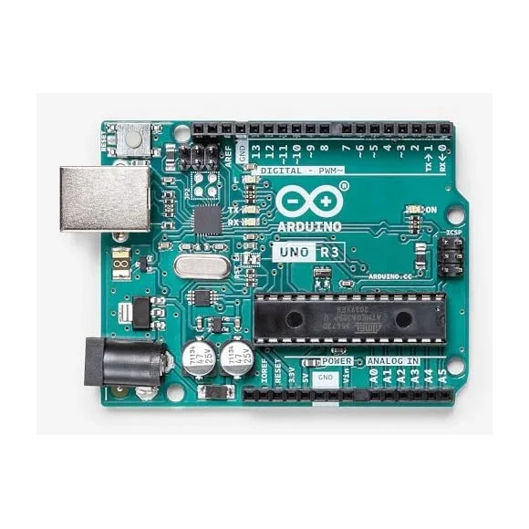
Arduino UNO
Hardware development board (SMD/DIP). ATmega328P, 14 digital I/O, 6 analog, USB-B.
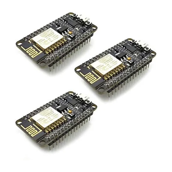
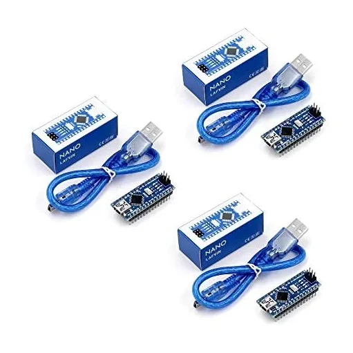
Arduino Nano
Compact development board. ATmega328P, mini-USB. Breadboard friendly.
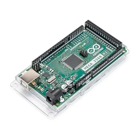
Arduino Mega
Development board. ATmega2560, 54 digital I/O, 16 analog, perfect for big projects.
 Out of stock
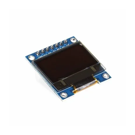
0.96 Inch Blue SPI OLED Display Module 7-Pin 128×64 – SSD1306
[LED/LCD Display] 0.96 Inch Blue SPI OLED Display Module 7-Pin 128×64 – SSD1306 The 0.96-inch Blue OLED Display Module is a compact graphical display based on the SSD1306 driver IC, featuring a 128×64 pixel resolution and blue monochrome display. This version has a 7-pin interface with a dedicated CS (Chip Select) pin, making it suitable for 4-wire SPI communication. The module is factory-configured for SPI and can also be modified for I2C/IIC communication on compatible board versions. With its compact size, wide viewing angle and low-power OLED technology, it is suitable for Arduino, ESP32, ESP8266, STM32, Raspberry Pi and other microcontroller projects. ⭐ Key Features 0.96-inch blue OLED display 128 × 64 pixel resolution SSD1306 driver IC 7-pin interface Dedicated CS (Chip Select) pin Factory configured for 4-wire SPI Supports SPI and I2C/IIC with appropriate configuration 3.3V/5V compatible on supported module versions No backlight required Low power consumption Wide viewing angle of more than 160° Compact PCB design Pre-soldered 7-pin male header Compatible with Arduino, ESP32, ESP8266, STM32 and Raspberry Pi projects 📋 Technical Specifications Display Type: OLED (Organic Light-Emitting Diode) Display Colour: Blue Display Size: 0.96 inch Driver IC: SSD1306 Resolution: 128 × 64 pixels Interface: SPI / I2C Default Interface: 4-wire SPI Input Voltage: 3.3V–5V Viewing Angle: >160° Module Dimensions: Approximately 27 × 27 × 4mm Operating Temperature: Approximately -30°C to +70°C Header: 7-pin male header, pre-soldered Display Type: Monochrome blue OLED 🔌 7-Pin Interface The 7-pin version provides the following connections: GND – Ground VCC – Power supply D0 / SCK / CLK – SPI clock D1 / MOSI / SDA – SPI data RES / RST – Display reset DC / A0 – Data/Command selection CS – Chip Select 🛠️ SPI Connection The module is normally supplied in 4-wire SPI configuration. For an Arduino Uno, a typical connection is: VCC → 5V GND → GND D0 → SCK / D13 D1 → MOSI / D11 RES → Digital I/O DC → Digital I/O CS → Digital I/O The dedicated CS pin allows the OLED to share the SPI bus with other devices such as SD cards or additional SPI peripherals. 🔄 I2C / IIC Configuration On compatible versions, the module can be converted from SPI to I2C by changing the appropriate resistor configuration on the PCB. The supplied board configuration may require: Moving the resistor from R3 to R1 Shorting R8 with solder Using D0 as SCL Using D1 as SDA Configuring DC for the I2C address The exact resistor positions can vary between board revisions, so check the markings on your particular PCB before modification. 🎯 Applications Arduino projects ESP32 projects ESP8266 projects STM32 development Raspberry Pi projects IoT devices Sensor displays Voltage/current meters Battery monitors Temperature displays Digital clocks Data loggers Portable electronic devices Robotics DIY measuring instruments Embedded systems Menu and status displays 💡 Advantages of OLED OLED technology is self-emissive, meaning the pixels produce their own light and do not require a conventional backlight. This provides high contrast, compact construction and a wide viewing angle while keeping power consumption relatively low. ⚠️ Important Notes This is the 7-pin SPI version, not the 6-pin version. The module is normally configured for SPI communication. Check the PCB labels before connecting the module. Do not exceed the specified supply voltage. Although many versions support 5V operation, the exact voltage tolerance can vary between board revisions. I2C operation may require hardware resistor modification. The actual PCB layout and component markings may vary slightly between production batches. Display colour: Blue. Libraries such as Adafruit SSD1306 and U8g2 can be used with compatible microcontrollers. 📦 Package Includes 1 × 0.96 Inch Blue SPI OLED Display Module
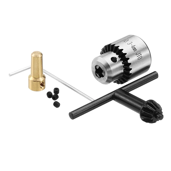
0.3–4mm Mini Drill Chuck with Key & 2.3mm Brass Shaft Adapter for 555 DC Motor
[General DC Motor] 🔧 0.3–4mm Mini Drill Chuck with Key & 2.3mm Brass Shaft Adapter for 555 DC Motor 0.3–4mm Chuck Capacity • JT0 Drill Chuck • 2.3mm Brass Shaft Adapter • Ideal for DIY Mini Drill Machines The 0.3–4mm Mini Drill Chuck with Key and 2.3mm Brass Shaft Adapter is a high-quality accessory designed for converting 555 DC motors into compact mini drilling machines. This complete set includes a precision JT0 drill chuck, a 2.3mm brass motor shaft adapter, and a chuck key for secure tightening and loosening of drill bits. Manufactured from high-carbon steel, the drill chuck provides excellent durability, wear resistance, and high clamping accuracy. It securely holds drill bits ranging from 0.3mm to 4.0mm, making it suitable for precision drilling in wood, plastic, acrylic, PCB boards, resin, aluminum, and other soft materials. The included 2.3mm brass shaft adapter offers a precise fit on 555 DC motor shafts, ensuring smooth power transmission with minimal vibration. Its corrosion-resistant brass construction provides excellent durability and reliable performance for long-term use. This mini drill chuck kit is widely used in DIY mini drill machines, PCB drilling, model making, hobby crafts, jewelry making, electronics repair, and educational projects. ⭐ Features Precision 0.3–4mm JT0 mini drill chuck Includes 2.3mm brass shaft adapter High-carbon steel chuck construction Brass motor shaft connector Secure key-operated chuck mechanism High clamping accuracy Strong impact and wear resistance Smooth and stable operation Easy installation on 555 DC motors Suitable for DIY mini drill machines Compatible with drill bits from 0.3mm to 4mm Compact and lightweight design 📋 Technical Specifications Product Type: Mini Drill Chuck Kit Chuck Capacity: 0.3mm – 4.0mm Chuck Type: JT0 Keyed Drill Chuck Chuck Material: High-Carbon Steel Adapter Material: Brass Motor Shaft Diameter: 2.3mm Connection Type: JT0 Taper Tightening Method: Chuck Key Compatible Motor: 555 DC Motor Application: Mini Electric Drill Conversion Color: Silver & Brass 🔧 Applications Suitable for: DIY Mini Drill Machines 555 DC Motor Projects PCB Drilling Electronics Repair Model Making Jewelry Making Woodworking Plastic Drilling Acrylic Drilling Resin Crafts Hobby Projects Educational Projects Small Precision Drilling Prototype Development 📦 Package Includes 1 × 0.3–4mm JT0 Mini Drill Chuck 1 × Chuck Key (Spanner) 1 × 2.3mm Brass Shaft Adapter ⚠️ Note Designed for 2.3mm diameter motor shafts. Recommended for 555 DC motors and compatible motors with a 2.3mm shaft. Suitable for drilling soft materials such as wood, plastic, acrylic, PCB, and aluminum. Not intended for heavy-duty industrial drilling or hammer drilling applications. Product appearance may vary slightly depending on the manufacturing batch.
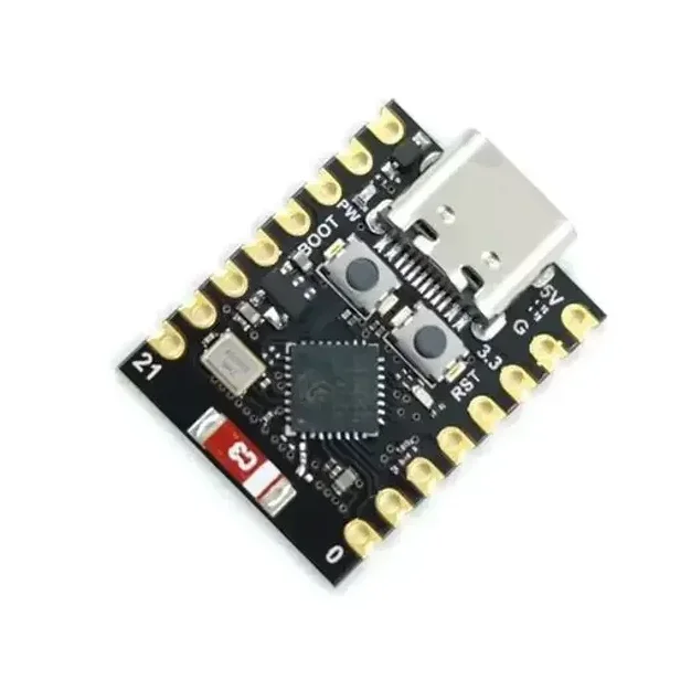
ESP32-C3 Super Mini Development Board With Headers Pins
[ESP Modules] Ultra Compact • Wi-Fi & BLE 5.0 • USB Type-C • Perfect for IoT & Embedded Projects The ESP32-C3 Super Mini Development Board is a compact, feature-rich development board built around the powerful ESP32-C3 SoC from Espressif. Powered by a 32-bit RISC-V single-core processor running at up to 160MHz, it combines 2.4GHz Wi-Fi, Bluetooth 5.0 Low Energy (BLE), and low-power operation in an ultra-small form factor. Designed for IoT, smart home, wireless communication, automation, and embedded system development, the ESP32-C3 Super Mini offers 4MB Flash memory, 400KB SRAM, multiple GPIOs, ADC, PWM, UART, SPI, and I2C interfaces for connecting sensors, displays, relays, and other peripherals. The onboard USB Type-C interface simplifies programming and power supply, while the built-in USB-to-Serial functionality enables quick firmware uploading without requiring additional programmers. Fully compatible with Arduino IDE, ESP-IDF, PlatformIO, and MicroPython, it is suitable for beginners, students, makers, and professional developers. Its ultra-compact breadboard-friendly design makes it ideal for portable and space-constrained projects where performance, wireless connectivity, and energy efficiency are essential. Note: Programming, software configuration, driver installation, firmware flashing, and coding-related issues are not covered under return or replacement. Users are expected to troubleshoot software-related issues independently. ⭐ Features Powerful ESP32-C3 32-bit RISC-V processor CPU frequency up to 160MHz Built-in 2.4GHz Wi-Fi (802.11 b/g/n) Integrated Bluetooth 5.0 Low Energy (BLE) Ultra-compact Super Mini design Breadboard-friendly layout USB Type-C interface for programming and power 4MB onboard Flash memory 400KB SRAM Multiple GPIO, ADC, PWM, UART, SPI & I2C interfaces Low power consumption with Deep Sleep mode Onboard programmable LED Compatible with Arduino IDE, ESP-IDF, PlatformIO & MicroPython Ideal for IoT, automation, robotics, and wireless applications 📋 Technical Specifications Product Type: Development Board Board Model: ESP32-C3 Super Mini Microcontroller: ESP32-C3 Processor Architecture: 32-bit RISC-V CPU Frequency: Up to 160MHz Core: Single Core Flash Memory: 4MB SRAM: 400KB Wi-Fi Standard: IEEE 802.11 b/g/n (2.4GHz) Bluetooth: Bluetooth 5.0 Low Energy (BLE) Operating Voltage: 3.3V Input Voltage: 5V via USB Type-C or 3.3V External USB Interface: USB Type-C GPIO: Multiple Digital GPIO Pins Analog Input: Up to 6 ADC Channels PWM: Supported UART: Supported SPI: Supported I2C: Supported USB-to-Serial: Onboard Onboard LED: User Programmable (GPIO8) Power Consumption: Ultra Low (Deep Sleep ≈ 43µA) Dimensions: Approx. 22.5 × 18 mm Headers: Pre-Soldered 🔧 Applications Suitable for: Internet of Things (IoT) Smart Home Automation Wireless Sensor Networks Home Automation Systems Bluetooth Low Energy Devices Wi-Fi Enabled Controllers Robotics Projects Data Logging Systems Remote Monitoring Industrial Automation Portable Embedded Devices Educational Learning DIY Electronics Projects Wearable Electronics Rapid Prototyping 📦 Package Includes 1 × ESP32-C3 Super Mini Development Board Pin Headers ⚠️ Note Programming, firmware installation, software configuration, and driver-related issues are not covered under warranty, return, or replacement. Please verify board compatibility and install the appropriate development environment before programming. Soldered and non-soldered header pin depend on stock
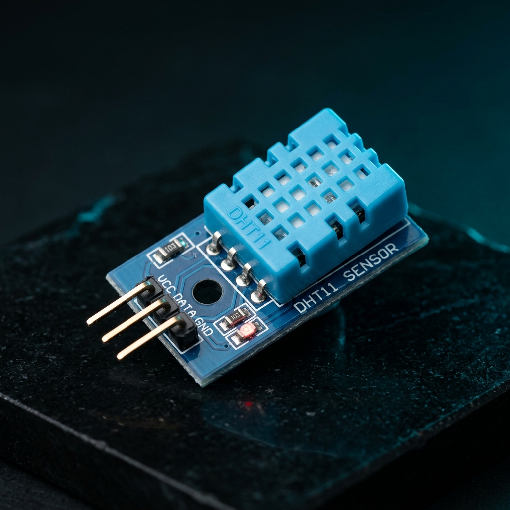
DHT11 Digital Temperature and Humidity Sensor Module 3.3V-5V for Arduino & Raspberry Pi
[Temperature Sensor] The DHT11 Digital Temperature and Humidity Sensor Module is a reliable and cost-effective sensor designed to measure ambient temperature and relative humidity. It combines a capacitive humidity sensing element and a thermistor with a built-in digital signal processing unit, providing calibrated digital output directly to microcontrollers. In addition, the DHT11 offers stable performance and excellent long-term reliability, making it suitable for environmental monitoring and automation applications. As a result, it is widely used in weather stations, smart home systems, greenhouse monitoring, HVAC systems, and educational electronics projects. Because the module includes the required pull-up resistor, interfacing with microcontrollers becomes simple and straightforward. Furthermore, only three connections are required: VCC, GND, and Data Output. The sensor operates from a wide voltage range of 3.3V to 5.5V DC, ensuring compatibility with Arduino, Raspberry Pi, ESP32, STM32, NodeMCU, and other development boards. Moreover, readily available libraries and example codes allow quick integration into projects. The DHT11 utilizes advanced digital signal acquisition technology and dedicated temperature-humidity sensing techniques to ensure accurate and dependable measurements. 🔹 Key Features Measures temperature and humidity simultaneously Calibrated digital signal output Low power consumption High reliability and long-term stability Capacitive humidity sensing technology Built-in pull-up resistor on module Compatible with Arduino, ESP32, Raspberry Pi, and STM32 Simple 3-wire interface Easy integration into IoT projects Compact and lightweight design 🔹 Technical Specifications Sensor Model: DHT11 Operating Voltage: 3.3V – 5.5V DC Output Type: Digital Serial Output Humidity Measurement Range: 20%RH – 90%RH Humidity Accuracy: ±5%RH Humidity Resolution: 1%RH Temperature Measurement Range: 0°C – 50°C Temperature Accuracy: ±2°C Temperature Resolution: 1°C Sampling Rate: 1Hz (One Reading Per Second) Long-Term Stability: < ±1%RH/Year Interchangeability: Fully Interchangeable Sensor Technology: Capacitive Humidity Sensor + Thermistor 🔹 Pin Configuration Pin 1 (VCC): 3.3V – 5.5V DC Power Supply Pin 2 (DATA): Digital Serial Data Output Pin 3 (GND): Ground 🔹 Applications This sensor module is suitable for: Arduino projects Raspberry Pi projects ESP32 projects IoT systems Weather monitoring stations Smart home automation Greenhouse monitoring HVAC control systems Environmental monitoring Educational electronics projects 🔹 Package Includes 1 × DHT11 Digital Temperature and Humidity Sensor Module
 Out of stock
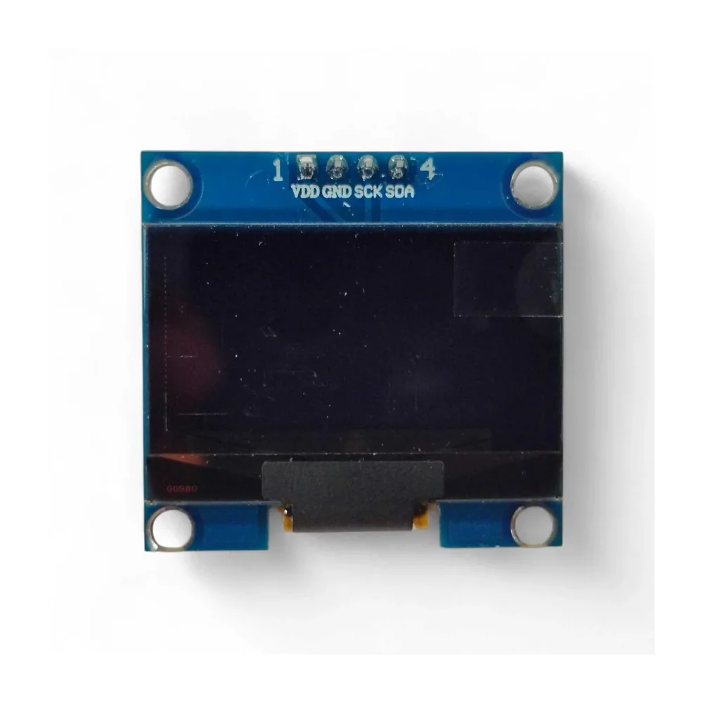
1.3 Inch I2C IIC 128×64 OLED Display Module – White
[LED/LCD Display Module] The 1.3 Inch I2C 128×64 OLED Display Module is a compact, high-contrast display designed for Arduino, ESP32, NodeMCU, Raspberry Pi, and other microcontroller-based projects. This module uses OLED (Organic Light Emitting Diode) technology, providing bright white pixels with excellent contrast and wide viewing angles. Powered by the SSH1106 controller chip, the display offers smooth graphics rendering and reliable performance. With a resolution of 128×64 pixels, it can display text, graphics, icons, and sensor data clearly even in small embedded systems. The module communicates using the I2C (IIC) interface, requiring only 4 pins (VCC, GND, SDA, SCL), which helps save valuable GPIO pins on your microcontroller. It operates within a voltage range of 3.3V to 5V, making it compatible with most development boards. Unlike traditional LCD displays, OLED displays do not require a backlight because each pixel emits its own light. This results in lower power consumption, better contrast, and faster response times. Due to its compact size, lightweight design, and simple wiring, the display module is ideal for IoT devices, sensor monitors, battery indicators, portable electronics, robotics projects, and DIY electronics applications. ⭐ Features 1.3 Inch OLED Display Module 128 × 64 pixel resolution White pixel display SSH1106 display controller I2C / IIC communication interface Requires only 4 pins High contrast and wide viewing angle Low power consumption Compatible with Arduino, ESP32, NodeMCU, Raspberry Pi Ideal for embedded and IoT projects 🔧 Technical Specifications Display Size: 1.3 inch Resolution: 128 × 64 pixels Controller Chip: SSH1106 Display Area: 34.5 × 19 mm Interface Type: IIC / I2C Pixel Color: White Driving Voltage: 3.3V – 5V Operating Temperature: -40°C to 70°C Physical Dimensions Length: 35.5 mm Width: 33.5 mm Height: 4 mm Weight: 7 g 📦 Package Includes 1 × 1.3 Inch 128×64 OLED Display Module (White)
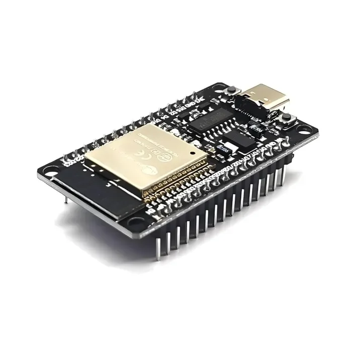
ESP32 Development Board with WiFi & Bluetooth – CH340C USB Type-C
[ESP Modules] The ESP32 Development Board with WiFi & Bluetooth (CH340C, Type-C) is a powerful and versatile microcontroller board designed for modern wireless and IoT applications. It features a dual-core processor and integrated 2.4GHz WiFi and Bluetooth (Classic + BLE) connectivity. This board includes an onboard CH340C USB-to-Serial converter, which allows easy programming and communication without requiring an external crystal oscillator. The USB Type-C port provides a stable and reversible connection for power and data. With a wide range of GPIO pins and peripherals such as ADC, DAC, PWM, UART, SPI, and I2C, this board is perfect for building home automation systems, smart devices, IoT nodes, robotics controllers, sensor networks, web servers, and wireless projects. It is fully compatible with Arduino IDE, ESP-IDF, and MicroPython, making it suitable for beginners, students, and professional developers. 🔹 Key Features Based on ESP32 dual-core microcontroller Built-in WiFi 802.11 b/g/n and Bluetooth v4.2 (Classic + BLE) Onboard CH340C USB-to-Serial converter (no external crystal required) Modern USB Type-C connector for power and programming Dual-core CPU up to 240 MHz for high-performance applications Multiple GPIO pins with ADC, DAC, PWM support Supports Arduino IDE, ESP-IDF, and MicroPython Low-power modes including deep sleep for battery-powered projects Compact design with breadboard-friendly layout Ideal for IoT, automation, robotics, smart home, and DIY electronics 🔹 Technical Specifications Microcontroller: ESP32 CPU: Dual-core Tensilica LX6, up to 240 MHz Flash Memory: 4 MB (typical, may vary by batch) SRAM: 520 KB Wireless Connectivity: WiFi: 2.4 GHz, 802.11 b/g/n Bluetooth: v4.2, Classic + BLE USB Interface: USB Type-C USB-to-Serial Chip: CH340C Operating Voltage: 3.3 V Input Voltage: 5 V via USB Logic Level: 3.3 V GPIO Pins: 30+ multifunction pins Peripherals: ADC, DAC, PWM, UART, SPI, I2C, I2S Clock Frequency: Up to 240 MHz Programming Support: Arduino IDE, ESP-IDF, MicroPython Onboard Components: Reset & Boot buttons, voltage regulator, status LEDs Form Factor: Standard ESP32 Dev Board size 🔹 Applications Internet of Things (IoT) projects Home and industrial automation Smart home devices Robotics and motor control Wireless sensor networks Web servers and cloud-connected devices Educational and training projects DIY electronics and prototyping 🔹 Package Contents 1 × ESP32 Development Board with WiFi & Bluetooth (CH340C, USB Type-C)
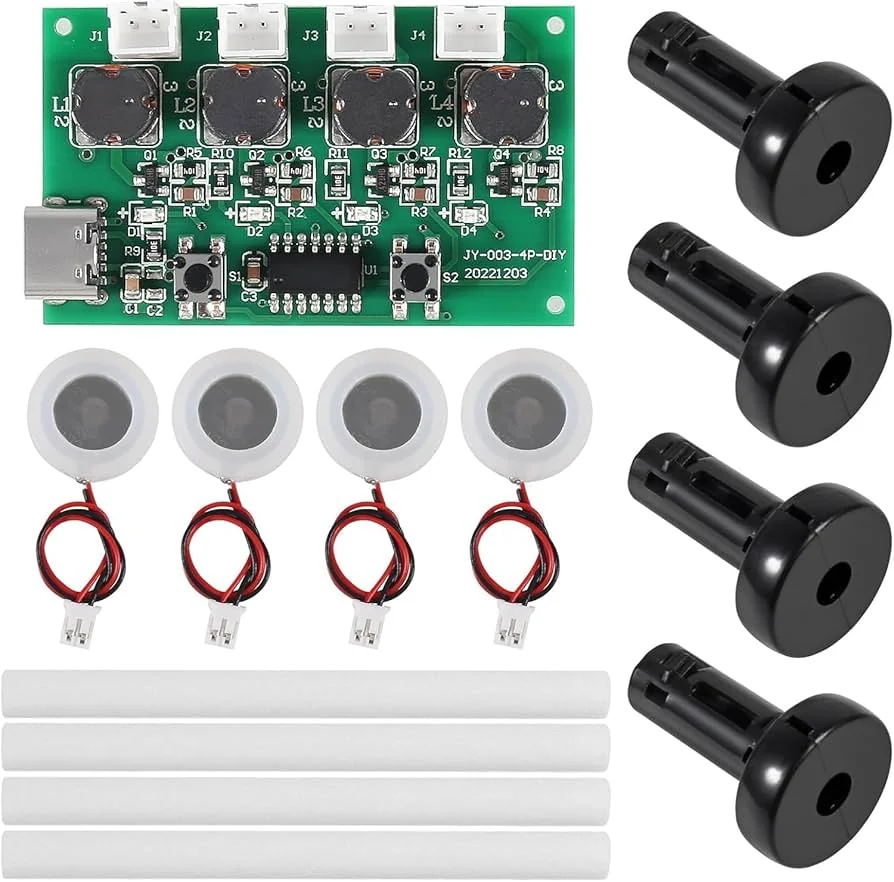
Type-C USB Mini Humidifier DIY Kit 4 in 1 | 4-Fogger Mist Maker Module | Ultrasonic Atomizer Film Sheet with Driver Board
[Ultrasonic Sensor] The Type-C USB Mini Humidifier DIY Atomizer Kit is a compact ultrasonic mist generation module designed for building or repairing USB-powered humidifiers, aroma diffusers, and fogging systems. Powered directly from a 5V USB Type-C source, the kit features a high-performance driver board and four ultrasonic ceramic atomizer discs that generate a dense, cool mist with low power consumption. Using advanced 108KHz ultrasonic atomization technology, the module converts water into ultra-fine mist particles without producing heat or mechanical noise. The stable driver circuit ensures reliable oscillation, efficient mist production, and long service life, making it an excellent choice for DIY enthusiasts, students, makers, repair technicians, and electronics hobbyists. Simply connect the module to a 5V USB Type-C power source, place the atomizer discs in water, and enjoy instant cool mist generation. It is compatible with custom humidifier enclosures, bottles, containers, 3D-printed projects, hydroponic systems, and decorative fog applications. ⭐ Features USB Type-C powered (5V DC) Four ultrasonic ceramic atomizer discs High-density cool mist output Advanced ultrasonic atomization technology Stable driver circuit for reliable operation Low power consumption Silent operation with no moving parts Compact and lightweight design Easy plug-and-play installation Ideal for DIY humidifiers and aroma diffusers 📋 Technical Specifications Product Type: USB Ultrasonic Humidifier Driver Kit Power Input: USB Type-C Female Operating Voltage: DC 4.5V–5V Input Voltage: 5V USB Operating Current: 300mA (Typical) Power Consumption: 2.5W–3W Rated Power: 2W Operating Frequency: 108KHz ±2KHz Atomizer Quantity: 4 Ceramic Atomizer Discs Atomization Technology: Ultrasonic Mist Output: High Density Fine Mist Driver Board: Ultrasonic Oscillation Control Module Cooling Method: Natural Cooling Power Connector: USB Type-C Female Socket Material: Ceramic Atomizer Discs + PCB Driver Board 🔧 Applications Suitable for: DIY USB Humidifiers Aroma Diffusers Replacement Humidifier Modules Decorative Fog Makers Hydroponic Systems Smart Garden Projects Terrariums & Vivariums Indoor Plant Humidification Science & Educational Projects Prototype Development DIY Electronics Projects 📦 Package Includes 1 × Ultrasonic Driver Circuit Board 4 × Ceramic Ultrasonic Atomizer Discs ⚠️ Note Use only clean water for optimal performance and longer atomizer life. Do not operate the module without water. Product images are for illustrative purposes only. The actual product may vary slightly depending on the manufacturing batch.
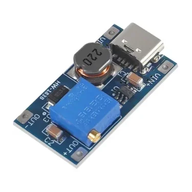
Type-C MT3608 Adjustable Dc to Dc Converter 2-24V to 5V-28V 2A
[Step UP Buck Converter] DC-DC Adjustable Boost Power Supply Module 2V–24V to 5V/9V/12V/28V 2A Type-C The DC-DC Adjustable Boost Power Supply Module is a compact step-up power conversion module designed to increase a lower DC input voltage to a higher adjustable output voltage. It supports a wide 2V–24V input range and provides an adjustable output from approximately 5V to 28V, making it suitable for battery-powered devices, microcontrollers, sensors, portable electronics and DIY power projects. With a compact 30 × 17 × 8mm design and Type-C connector, this module is convenient for projects where space and flexible power input are important. ⭐ Key Features DC-DC boost/step-up converter Wide 2V–24V input voltage range Adjustable output voltage Output options include approximately 5V, 9V, 12V and 28V Maximum output current: 2A Conversion efficiency: >93% Compact and lightweight design Type-C input connector Suitable for battery-powered applications Easy to integrate into DIY electronics projects 📋 Technical Specifications Product Type: DC-DC Boost Converter Module Input Voltage: 2V–24V DC Output Voltage: 5V–28V adjustable Maximum Output Current: 2A Peak Output Current: Up to 2A Efficiency: >93% Input Connector: USB Type-C Product Size: 30 × 17 × 8mm Weight: Approximately 4g Condition: New 🔧 Applications Arduino and microcontroller projects Raspberry Pi and electronic development projects Battery-powered devices Portable power systems GPS and sensor projects LED applications Robotics projects Motors and actuators DIY power supplies Low-voltage to higher-voltage power conversion Portable electronic equipment 🛠️ How It Works This module uses a DC-DC boost conversion circuit to increase the input DC voltage. For example: 3.7V battery → 5V output 5V input → 9V output 5V/12V input → higher adjustable output The required output voltage can be adjusted according to the application. ⚠️ Important Notes This is a boost/step-up module; the output voltage cannot be lower than the applicable input voltage range. Do not exceed the specified 24V maximum input voltage. Do not exceed the 2A maximum output current. Actual maximum output power depends on input voltage, output voltage, cooling and module operating conditions. At higher output power, adequate ventilation/cooling may be required. Always verify the output voltage with a multimeter before connecting sensitive electronics. Do not short-circuit the output. The module does not automatically regulate to 5V/9V/12V/28V; the output must be set to the required voltage. 📦 Package Includes 1 × DC-DC Adjustable Boost Module 2V–24V to 5V/9V/12V/28V, 2A, Type-C
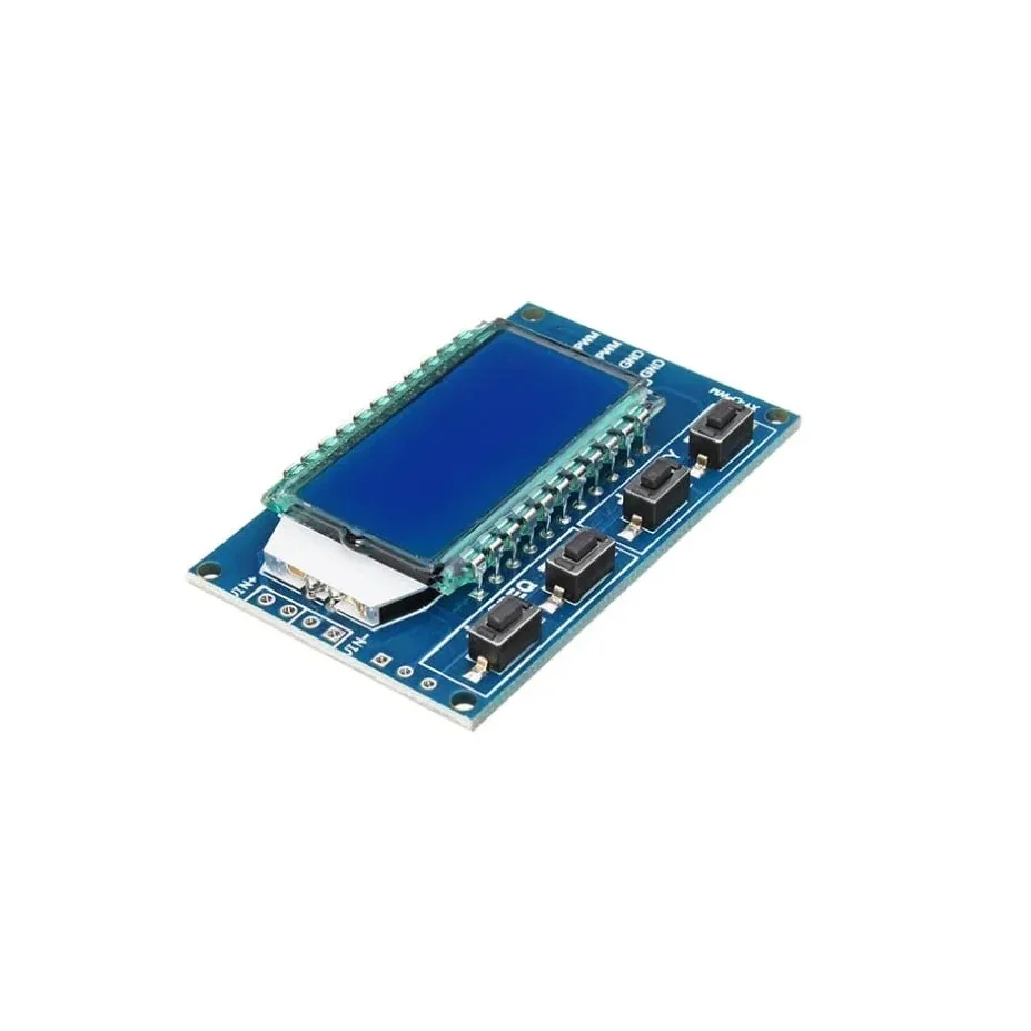
XY-LPWM Signal Generator PWM Pulse Frequency Duty Cycle Adjustable Module LCD Display Module
XY-LPWM Signal Generator PWM Pulse Frequency Duty Cycle Adjustable Module LCD Display Module is a two-channel PWM signal generator. It has dedicated switches for adjusting the frequency and duty cycle separately. Using this module PWM output, frequency and duty cycle can be set as per requirements. Communication Standard: 9600 bps Data bits: 8 Stop bit: 1 Check digit: none Flow control: none Set the frequency of the PWM “F101”: Set the frequency to 101 Hz (001 to 999) “F1.05”: set the frequency of 1.05 kHz (1.00 ~ 9.99) “F10.5”: Set the frequency to 10.5kHz (10.0 ~ 99.9) “F1.0.5”: set the frequency of 105kHz (1.0.0 ~ 1.5.0) Set the PWM duty cycle “DXXX”: set the PWM duty cycle to XXX; (001 ~ 100) Such as D050, set the PWM duty cycle is 50% Read the set parameters Send a “read” string to read the set parameters. Set successfully return: DOWN; Setup failed to return: FALL. Application: This is used to drive a stepper motor driver’s square wave. Generate an adjustable pulse for MCU. Generate an adjustable pulse for controlling relative circuit (PWM adjust lightspeed, etc). Used as a square wave signal generator for experimental development and use. Parameter Settings: The module has 4 switches, two for frequency adjustment and two for duty cycle adjustment. This module can generate frequencies between 1Hz and 150kHz, with automatic switching for different ranges. Frequency is divided into four ranges, automatic switching: 1. XXX (no decimal point): the smallest unit is 1Hz, the value range of 1Hz ~ 999Hz; 2. X.XX (decimal point in the hundred) the smallest unit is 0.01Khz, the range of 1.00Khz ~ 9.99Khz; 3. XX.X (decimal point in ten): the smallest unit is 0.1Khz; value range of 10.0KHz ~ 99.9KHz 4. X.X.X (decimal point in ten and hundred): the smallest unit is 1Khz; value range 1KHz ~ 150KHz 5. e.g. frequency display: 100 indicates PWM output 100Hz pulse; 1.01 indicates PWM output 1.01K pulse; 54.1 indicates that the PWM output has a pulse of 54.1 kHz; 1.2.4 indicates that the PWM output is 124 kHz pulse; Duty cycle range: 1 – 100%. In case of a power outage or if the module is powered down, the parameters that are set are saved automatically, so there is no need to set the parameters again. Single touch for increasing or decreasing single unit and long press for fast increasing or decreasing. Features: LCD display for frequency and duty cycle. Wide frequency range. High precision. Serial communication(TTL based). Package Includes: 1 x XY-LPWM Signal Generator PWM Pulse Frequency Duty Cycle Adjustable Module LCD Display Module.
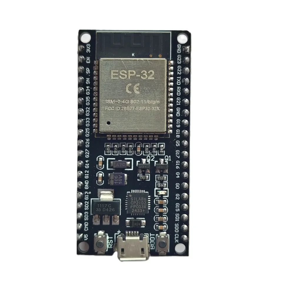
ESP32 38-Pin Development Board – IoT Microcontroller with WiFi & Bluetooth
[ESP Modules] Description The ESP32 38-Pin Development Board is a versatile and cost-effective microcontroller platform perfect for a wide range of IoT, automation, and wireless communication projects. Powered by the ESP32 SoC, this board offers integrated WiFi and Bluetooth (BLE) capabilities, making it ideal for developing smart home devices, industrial control systems, robotics, and DIY electronics. For the best IoT experience, you can pair this board with our LoRa SX1278 Module for long-range communication or integrate it with our 0.96-inch OLED Display for real-time data display. Need reliable power control? Combine it with our 2-Channel Relay Module with Optocoupler for safe switching of external devices. Compatible with popular platforms like Arduino IDE, MicroPython, and PlatformIO, this ESP32 board is user-friendly for both beginners and professionals. The board features 38 GPIO pins, enabling you to connect a variety of sensors, actuators, and other peripherals—available in our IoT Components category. Key Features: ESP32 Dual-Core 32-bit LX6 Processor Built-in 2.4 GHz WiFi and Bluetooth 4.2 (BLE) 38 GPIO Pins supporting multiple digital and analog functions Interfaces: UART, SPI, I2C, PWM, ADC, DAC Ultra-low power operation modes ideal for battery-powered IoT devices Supports Arduino IDE, MicroPython, and other environments Onboard micro-USB connector for easy power and programming Reset and boot buttons for firmware flashing Breadboard-friendly form factor Applications: IoT development projects Smart home automation – compatible with Vihaan IoT Gateway Solutions Wireless data logging systems Robotics and drone controllers Industrial monitoring devices Sensor networks – connect with our DHT11/DHT22 Temperature Sensors Specifications: Chipset: ESP32 (Generic) Operating Voltage: 3.3V (5V tolerant inputs) Flash Memory: 4MB Connectivity: WiFi IEEE 802.11 b/g/n, Bluetooth 4.2 BLE Interfaces: GPIO, UART, SPI, I2C, ADC, DAC, PWM USB Interface: Micro USB Form Factor: 38-Pin, breadboard compatible Package Includes: 1 x ESP32 38-Pin Generic Development Board
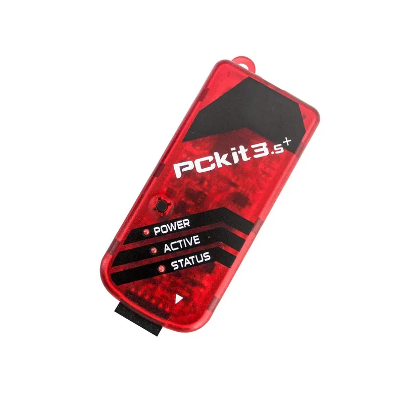
PICKIT3.5 Plus Microchip Programmer W/USB Cable Wires Pic Kit 3.5+
Description: PICKIT3.5 Plus In-Circuit Debugger/Programmer compatible with Microchip uses in-circuit debugging logic incorporated into each chip with Flash memory to provide a low-cost hardware debugger and programmer. The PICKIT3.5 Plus allows debugging and programming of PIC and dsPIC Flash microcontrollers using the powerful graphical user interface of the MPLAB Integrated Development Environment (IDE). PICKIT3.5 Plus is an upgrade from the Pickit 3 programmer with the programming-to-go feature. Specifications: Type: Debugger/Programmer Tool/Board Application: Debugging/Programming MCU Supported Families: Flash-based PIC MCUs Core Architecture: PIC, dsPIC IC Product Type: In-Circuit Debugger Features USB (Full speed 12 Mbits/s interface to host PC) Real-time execution MPLAB IDE compatible (free download from Microchip) Built-in over-voltage/short circuit monitor Firmware upgradeable from PC/web download Diagnostic LEDs (power, busy, error) Read/write program and data memory of the microcontroller Erase of program memory space with verification Freeze-peripherals at breakpoint Program up to 512K byte flash with the Programmer-to-Go ICSP cable included Package Included: 1 x PICKIT3.5 Plus Microchip Programmer W/USB Cable Wires Pic Kit 3.5+
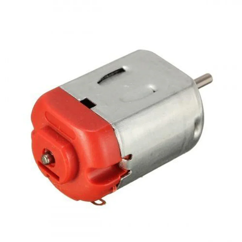
Micro 130 DC Motor 3V-6V High Speed Brushed DC Motor (9000–13000 RPM)
[General DC Motor] The Micro 130 DC Motor is a compact, lightweight, and high-performance brushed DC motor widely used in hobby electronics, robotics, educational kits, and battery-powered devices. Operating on 3V to 6V DC, it delivers a no-load speed of 9,000–13,000 RPM, making it suitable for applications requiring high-speed rotary motion in a compact form factor. Designed with a durable metal housing and a precision 2mm output shaft, this motor provides smooth operation, stable performance, and excellent reliability. Its compact dimensions make it easy to integrate into small electronic projects where space is limited. The motor can be easily connected to Arduino, Raspberry Pi, ESP32, motor driver modules, and other microcontroller platforms, making it an excellent choice for beginners, students, hobbyists, and professionals. Whether you're building a robot, smart car, mini fan, science experiment, or replacing a toy motor, the Micro 130 DC Motor offers dependable performance and long service life. ⭐ Features Compact and lightweight Micro 130 brushed DC motor Operating voltage from 3V to 6V DC High-speed operation up to 13,000 RPM Durable metal housing for long service life Precision 2mm output shaft Smooth and stable performance Low power consumption Easy two-wire connection Supports clockwise and counter-clockwise rotation Ideal for battery-powered applications Perfect for DIY electronics, robotics, and educational projects 📋 Technical Specifications Product Type: Brushed DC Motor Model: Micro 130 Operating Voltage: 3V – 6V DC Motor Speed: 9,000–13,000 RPM (No Load) Motor Type: Brushed DC No Load Current: 0.5A – 0.9A Shaft Diameter: 2mm Shaft Length: 8mm Rotation Direction: Clockwise (CW) / Counter-Clockwise (CCW) by reversing supply polarity Terminal Type: Solder Tabs Housing Material: Metal Weight: Approx. 18g 🔧 Applications The Micro 130 DC Motor is suitable for a wide range of applications, including: Robotics Projects Arduino Projects Raspberry Pi Projects ESP32 Projects RC Cars Toy Vehicles DIY Electronics Mini Cooling Fans Small Water Pumps Educational STEM Kits Science Experiments Battery-Operated Devices Automation Projects Prototype Development Hobby Electronics 📦 Package Includes 1 × Micro 130 DC Motor (3V–6V)Note: Product images are for reference only. The actual product may differ slightly due to manufacturing revisions or supplier changes. For bulk purchases, we recommend ordering a sample first or contacting customer support to verify the latest product images and specifications.
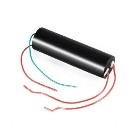
DC 3V-6V to 1000KV 1000000V Boost Step-up Power Module
[Step UP Buck Converter] Description Overview of this DC 3V-6V to 1000KV step up high voltage generator The DC 3.6V-6V To 1000KV Boost Step Up Power Module is a cutting edge high voltage generator designed for diverse applications. With a focus on safety and efficiency. This module easily transforms low input voltages of 3.6V to 6V into a powerful output up to 1000KV. Ideal for high-voltage experiments, education purposes, and prototype. It also provides a versatile solution for various electronic projects. Featuring advanced step-up DC conversion technology, this module ensures stable and reliable performance. Its compact design also make it perfect for use in a wide range of projects. The input range of 3V-6V offers flexibility, and the adjustable output allows users to fine-tune the voltage as needed. With a focus on user safety, the module includes built-in protective featur to prevent overloading and ensure efficient operation. This makes it an excellent choice for experimentation. And also enable users to observe and understand high-voltage principles while maintaining a reliable and secure environment. Elevate your projects with this versatile high-voltage generator, perfect for education institute, research lab. Features High Voltage Output for Varied Applications: The DC 3V-6V to 1000KV high voltage generator also contain a remarkable high voltage output. This capability opens the door to a wide range of experimental setups, scientific projects, and practical applications where such high voltage are important. Versatile Compatibility with Input Range: Operating easily within the input voltage range of 3.6V to 6V. This module offers versatility and compatibility with different power sources. This adaptability ensures its applicability across a diverse array of electronic projects. Compact and Space-Efficient Design: With dimensions 50mm x 30mm x 25mm, the module compact design provide easy integration into various electronic setups. Its space efficient form factor is ideal for projects with size constraints. Precision with Adjustable Output: The module provides users with the flexibility to fine-tune the output voltage according to specific project needs. This adjustability ensure precision in voltage control, catering to the needs of different applications. Enhanced Safety through Built-in Protection: This module prioritizes it by incorporating built in protection mechanism. These feature prevent over loading and ensure a secure and reliable high voltage generation experience. Specifications: Specification Value Input Voltage (V) 3.3V~5V DC Maximum Operating Current (A) 2 – 5 Max. Output Voltage 1000 KV Max. Output Current (A) 0.5 A Discharge Time 10s Color Black Length (mm) 8.8 Width (mm) 2.67 Height (mm) 2.3 Weight (gm) 45 Efficiency Up to 93% Main application of this DC 3V-6V to 1000KV step up high voltage generator High-Voltage Experiments and Demonstrations: This versatile DC 3V-6V to 1000KV Boost Step up Power Module is perfect for safely conduct a wide range of high voltage experiment. This module also use an important tool for showcase the principle of high voltage in a controlled environment. Education tools: Elevate your physics and electronics education with the inclusion of this module in class room activities. The adjustable high voltage output allows students to explore various aspects of electricity. And foster a hands on learning experience that enhance knowledge. Powering Electronic Projects: Integrate this module into your electronic projects that demand a reliable and adjustable high voltage power source. Its compact design and efficiency make it perfect to power various electronic applications where precise control over voltage is crucial for optimal project performance. Captivating Static Electricity: Capture the attention of audiences with captivating static electricity demonstrations. This module provides the necessary power to create visually striking and education displays. Research and Development in Electric Engineering: For professionals in electric engineering and researcher. This module also use a valuable asset in research and development. Its efficiency and versatility make it an ideal tool for testing projects in the field of electric engineering. Package Includes: 1 x 1000KV Step Up Power Module
 Out of stock
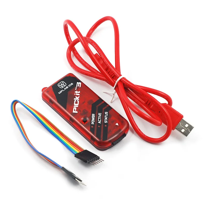
PICkit3 Debugger Programmer Emulator Controller Development Board
[Uncategorized] This is PICkit3 Debugger Programmer Emulator Controller Development board w/ Pinout diagram to ease the customer. The USB connection is more stable than ICD2. PICKIT3.5, begin to support Win7 system. Full patch design, patch through the reflow soldering processing, more stable quality. PIC developing data, C language development tool manual. A lot of PIC basic experiment program code; ICD2 PICKIT3 etc application specification. The MPLAB PICkit 3 allows debugging and programming of PIC® and dsPIC® Flash microcontrollers at a most affordable price point using the powerful graphical user interface of the MPLAB Integrated Development Environment (IDE). The MPLAB PICkit 3 is connected to the design engineer’s PC using a full-speed USB interface and can connect to the target via a Microchip debug (RJ-11) connector (compatible with MPLAB ICD 2, MPLAB ICD 3 and MPLAB REAL ICE). Pickit3 Pinout: Features : Full-speed USB support using Windows standard drivers Real-time execution Processors run at maximum speeds Built-in over-voltage/short circuit monitor Low voltage to 5V (1.8 to the 5V range) Read/write program and data memory of the microcontroller Diagnostic LEDs (power, active, status) Read/write program and data memory of the microcontroller 1Erase of all memory types (EEPROM, ID, configuration, and program) with verification Peripheral freeze at the breakpoint. Program up to 512K byte flash. Package Includes : 1 x PICKIT3 Programmer. 1 x USB cable 1x 6pin cable A DVD
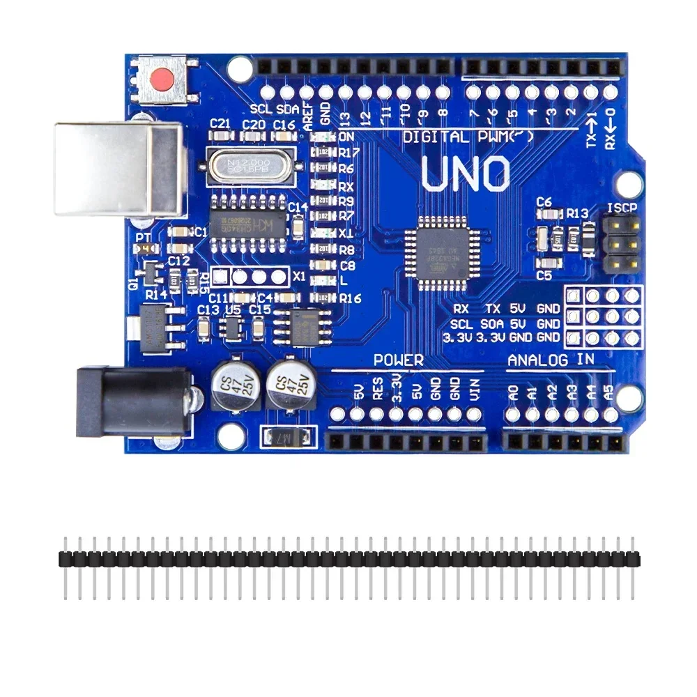
Arduino Uno R3 CH340G ATMega328P Development Board Compatible with Arduino
[Arduino Boards, Development Board] Product Description The Uno R3 CH340G ATmega328p Development Board is the low-cost version of the popular Uno R3 Arduino. It is assembled with the CH340 USB to Serial converter chip, instead of using an Atmega16U2 chip. We have used plenty of these low-cost Arduino boards with CH340 chips, and have found them to work perfectly. The only time the CH340 chip is used is during programming and when using the serial output of the USB port. During normal operation, this board is identical to the more expensive version without CH340 chip. Features The Arduino Uno R3 is a micro-controller board base on the ATmega328 . It has 14 digital input/output pins (of which 6 can be used as PWM outputs); 6 analog inputs, a 16 MHz ceramic resonator, a USB connection, a power jack, an ICSP header, and a reset button. It contains everything need to support the micro-controller; simply connect it to a computer with a USB cable or power it with a AC-to-DC adapter or battery to get start. The Arduino Uno R3 differs from all preceding boards in that it does not use the FTDI USB-to-serial driver chip. Instead, it features the Atmega16U2 (Atmega8U2 up to version R2) program as a USB-to-serial converter. Revision 2 of the Uno board has a resistor pulling the 8U2 HWB line to ground, making it easier to put into DFU mode. Note: The Arduino Uno R3 reference design can use an Atmega8, 168, or 328, Current models use an ATmega328, but an Atmega8 is shown in the schematic for reference. The pin configuration is identical on all three processors. Package Includes 1 x Arduino Uno R3 CH340G ATMega328P Development Board
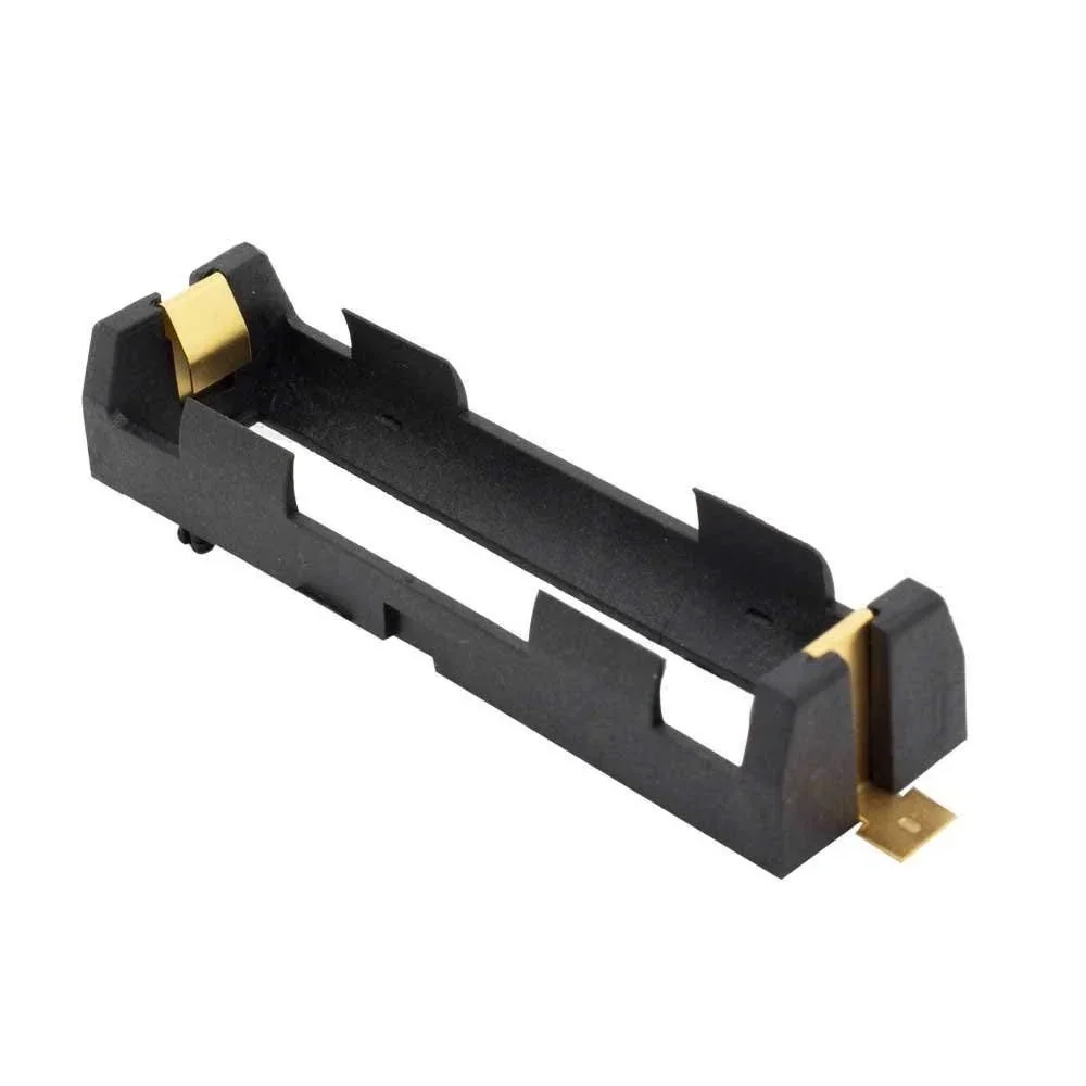
18650 SMD/SMT High-Quality Single Battery Holder
[Lithium Battery Holder] 18650 SMD/SMT High-Quality Single Battery Holder The 18650 SMD/SMT Single Battery Holder is a compact PCB-mount battery holder designed to securely hold a single 18650 Li-ion rechargeable cell. Its SMD mounting pins allow the holder to be directly soldered onto a PCB, eliminating the need for loose battery wires and making it suitable for compact electronic designs. Multiple electronics retailers list the same holder with ABS construction, gold-plated contacts, stainless-steel contact material and dimensions of approximately 77 × 21 × 15mm. ⭐ Key Features Designed for 1 × 18650 lithium-ion cell SMD/SMT PCB mounting design Lightweight and compact Directly mounts onto a PCB Eliminates loose battery wiring Gold-plated brass contact points Stainless-steel battery contact/shrapnel High-quality ABS body Secure battery holding mechanism Easy battery insertion and replacement Reusable design Good environmental and temperature resistance Suitable for compact PCB projects 📋 Technical Specifications Product Type: 18650 SMD/SMT Battery Holder Number of Cells: 1 Compatible Battery: 18650 Li-ion cylindrical cell Mounting Type: SMD / SMT Body Material: ABS Contact Material: Stainless Steel Contact Plating: Gold Contact Construction: Gold-plated brass contact points with stainless-steel battery retention contacts Color: Black Operating Temperature: -40°C to 180°C Dimensions: Approx. 77 × 21 × 15mm (L × W × H) Weight: Approx. 8g 🔋 Battery Compatibility This holder is designed specifically for a single 18650 cylindrical Li-ion cell. It provides mechanical support and electrical contacts between the battery and the PCB; the holder itself does not provide battery charging, overcharge protection or BMS functionality. 🔧 Applications PCB battery-powered projects DIY electronics Arduino projects ESP32 and microcontroller projects Robotics Portable electronic devices Battery-powered gadgets IoT devices Custom PCB designs Rechargeable battery projects Prototyping and development boards 🛠️ Installation Position the holder on the PCB according to the PCB footprint. Ensure the positive and negative contacts are correctly oriented. Solder the SMD terminals to the PCB. Allow the solder joints to cool and inspect them for proper connection. Insert a compatible 18650 battery with the correct polarity. Verify the battery voltage and circuit polarity before powering the project. 📦 Package Includes 1 × 18650 SMD/SMT High-Quality Single Battery Holder ⚠️ Precautions Use only a compatible 18650 cylindrical Li-ion cell. Check the positive and negative polarity before inserting the battery. The holder is only a mechanical/electrical battery holder; it does not include a charger or BMS. Do not short-circuit the contacts. Do not force an incorrectly sized battery into the holder. Ensure the PCB solder joints are secure before inserting the battery. Do not exceed the electrical limits of the holder or PCB. Remove the battery before soldering or servicing the PCB.
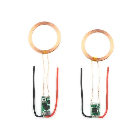
5V 1A Wireless Power Supply Transmitter Receiver Charging Coil Module
[Induction Module] Wireless Charger Module Inductive Charger Transmitter + Receiver Power Supply Module DC 5 V 1A This product is for the current wireless charging various series of small electronic products, and power development and design is made with a small size, extremely easy to use, high efficiency, low cost features primarily for mobile electronics products such as: cell phones, game machine, fish tank, MP3, MP4, adult products, digital cameras, electric shavers, machine learning, medical supplies and other products of underwater applications. As a result of non-contact charging power supply, make the product completely sealed, waterproof and dustproof, increase the life of the product easier to use. Features: Input voltage: 9 ~ 12V Maximum load current: 1.3A Receives the output voltage and current: 5V / 2A, 12V / 700mA Transmitting coil size: diameter 43mm, thickness 2.3mm Transmitter module size: 18mm * 8.5mm * 15mm Receiver Module size: 10mm * 25mm * 3mm Receiving coil size: diameter 43mm, thickness 1.2mm Receive the best distance: 3 ~ 6mm Includes: Power Transmitter Power Receiver
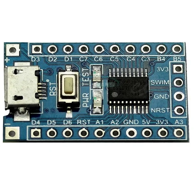
Core Board STM8S103F3P6 STM8 Development Board Minimum System Board
[Development Board] Connection Diagram: Features : Chipboard STM32F103C8T6 On board, SWIM interface and reset button Micro USB line or the 2.54 pin to link to the power with the input voltage 4.5V-15V. Power light and the Demo indicator light Leads all the pins and has detailed label for the Pins. Support SWIM debug mode. Package Includes : 1 x Core Board STM8S103F3P6 STM8 Development Board
 Out of stock
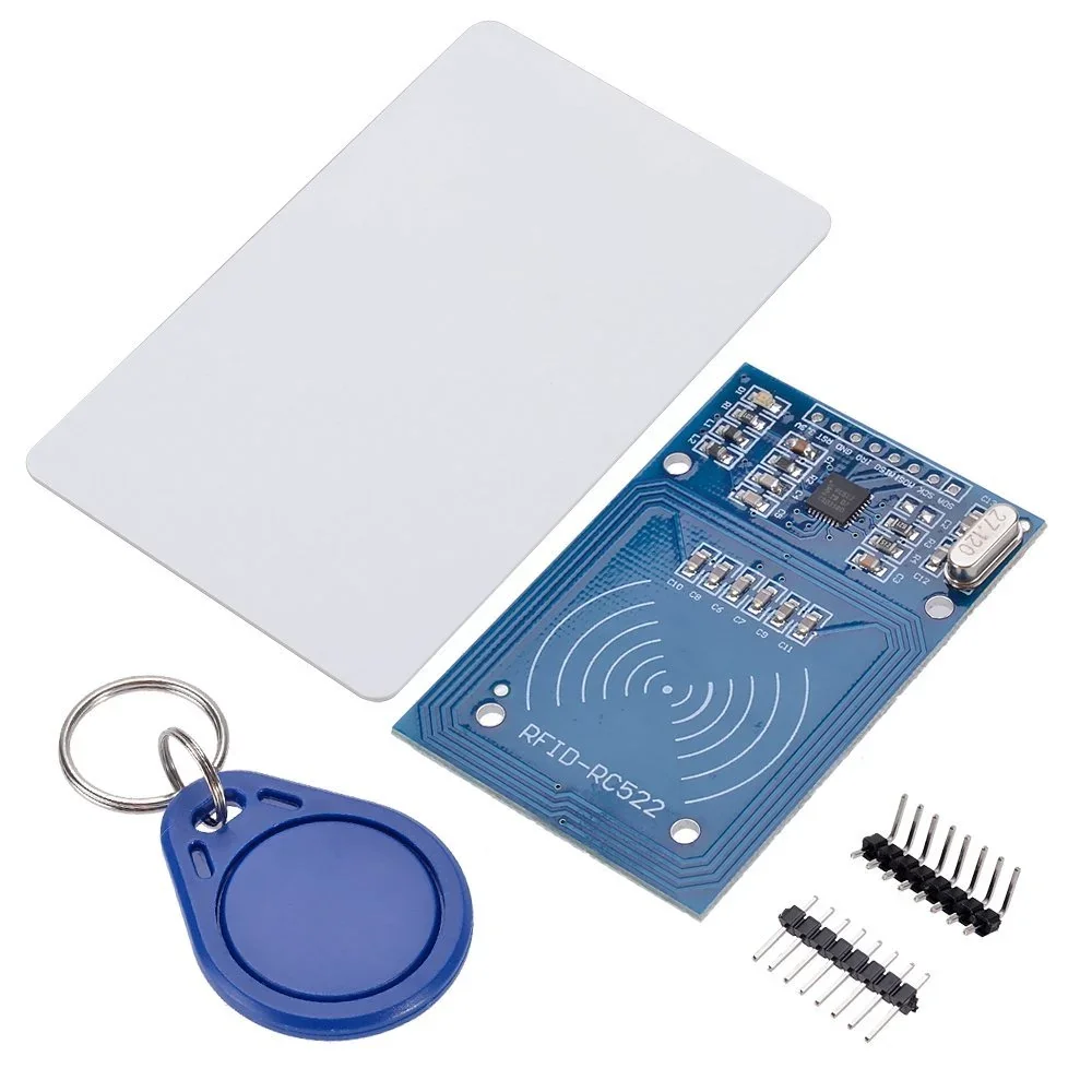
RFID Reader/Writer RC522 SPI S50 with RFID Card and Tag
[IR and PIR Sensors] Do you want to know the work of RFID Reader/Writer RC522 SPI S50 CARD AND KEYCHAIN, then this Product is best for you . With this Product, you can detect radio waves produced by a reader to detect the presence of (then read the data stored on) an RFID tag This is RFID Reader/Writer RC522 SPI S50 CARD AND KEYCHAIN which works on non-contact 13.56mhz communication, is designed by NXP as low power consumption, low cost, and compact size read and write chip, is the best choice in the development of smart meters and portable hand-held devices. It uses an advanced modulation system, fully integrated at 13.56MHz with all kinds of positive non-contact communication protocols. Support 14443A compatible answer signal. DSP deals with ISO14443A frames and error correction. This module can fit directly in handheld devices for mass production. The module uses the 3.3V power supply and can communicate directly with any CPU board by connecting through the SPI protocol, which ensures reliable work, good reading distance. Features : Highly integrated analog circuitry to demodulate and decode responses. Supports ISO/IEC 14443 A/MIFARE. Typical operating distance in reading/Write mode up to 50 mm. Supports ISO/IEC 14443 A higher transfer speed communication up to 848 kBd. SPI up to 10 Mbit/s. FIFO buffer handles 64 bytes send and receive. Flexible interrupt modes. Power-down by software mode. Programmable Timer. 2.5 V to 3.3 V power supply. CRC coprocessor. Internal self-test. Package Includes 1 x RFID-RC522 Reader/Write Module 1 x Standard blank RFID card 2 x A Straight & right-angle header strip 1 x Special-shaped keychain RFID tag
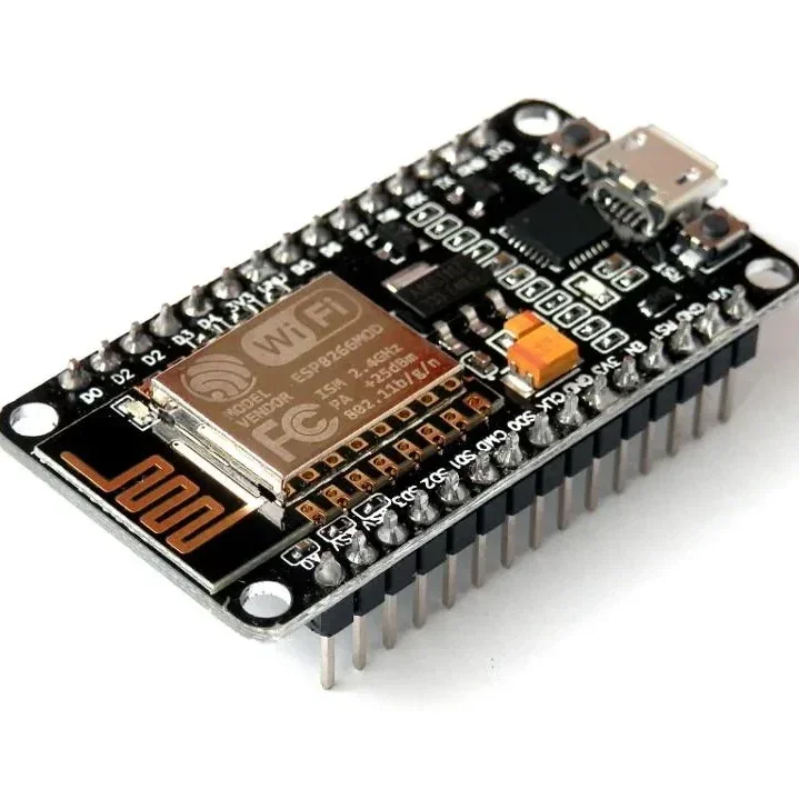
ESP8266 NodeMCU CP2102 ESP-12E WiFi Development Board
[ESP Modules] ESP8266 NodeMCU CP2102 ESP-12E WiFi Development Board ESP8266 ESP-12E • CP2102 USB Interface • Built-in WiFi • Arduino & Lua Compatible • IoT Development Board The ESP8266 NodeMCU CP2102 ESP-12E WiFi Development Board is a compact and powerful development board designed for IoT (Internet of Things), wireless communication, home automation, robotics, and embedded system projects. Based on the highly popular ESP8266 ESP-12E WiFi module, it combines a 32-bit microcontroller, WiFi connectivity, and a CP2102 USB-to-Serial interface on a single breadboard-friendly board. The board comes preloaded with NodeMCU firmware, allowing easy programming using Lua scripting, while also offering full compatibility with the Arduino IDE, making it suitable for both beginners and advanced developers. With integrated 802.11 b/g/n WiFi, TCP/IP networking, multiple GPIO pins, PWM, I2C, SPI, and UART interfaces, it provides everything required for rapid IoT prototyping and wireless application development. The onboard CP2102 USB interface, 3.3V voltage regulator, and logic-level conversion circuitry allow direct connection to a computer for programming and power, eliminating the need for external USB-to-Serial converters. ⭐ Features ESP8266 ESP-12E WiFi module Built-in CP2102 USB-to-Serial interface 802.11 b/g/n WiFi connectivity Integrated TCP/IP protocol stack 32-bit processor with onboard memory Compatible with Arduino IDE, Lua, and NodeMCU firmware Breadboard-friendly compact design Multiple GPIO pins Supports PWM, I2C, SPI, and UART Onboard 3.3V voltage regulator Logic-level conversion circuitry included Low power consumption Ideal for IoT and wireless projects Easy plug-and-play programming 📋 Technical Specifications Product Type: WiFi Development Board Model: ESP8266 NodeMCU ESP-12E Microcontroller: ESP8266EX WiFi Standard: IEEE 802.11 b/g/n USB Interface: CP2102 Operating Voltage: 3.3V Input Voltage: 5V via Micro USB Flash Memory: 4MB CPU: 32-bit Tensilica L106 Clock Frequency: 80MHz / 160MHz GPIO Pins: Multiple Digital I/O Communication Interfaces: UART, SPI, I2C PWM Support: Yes ADC: 1 Channel (10-bit) USB Connector: Micro USB Firmware: NodeMCU (Preloaded) Programming Support: Arduino IDE, Lua, ESP8266 SDK Board Size: Approx. 58 × 31 mm 🔧 Applications IoT (Internet of Things) Projects Home Automation Smart Lighting Systems WiFi Sensor Nodes Wireless Data Logging Robotics Projects Arduino WiFi Projects ESP8266 Development Remote Monitoring Systems MQTT Applications Web Server Projects Smart Agriculture Industrial Automation DIY Electronics Educational Projects 📦 Package Includes 1 × ESP8266 NodeMCU CP2102 ESP-12E WiFi Development Board ⚠️ Note Operates at 3.3V logic levels. Install the CP2102 USB driver if the board is not detected by your computer. Use a good quality Micro USB cable for programming and power. Product appearance may vary slightly depending on the manufacturing batch.