
All products · 22 of 1440
Electronics, sensors, robotics kits, PC components, peripherals — everything Unik Systems carries, in one place.
 Out of stock
Xbox Elite Wireless Controller Series 2
Adjustable trigger tension, swappable paddles, 40-hour battery.
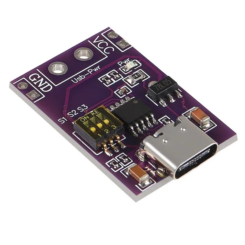
Type-C PD/QC/AFC Fast Charge Decoy Trigger Module – 5V/9V/12V/15V/20V Fixed Output
[Step UP Buck Converter] Type-C PD/QC/AFC Fast Charge Decoy Trigger Module – 5V/9V/12V/15V/20V Fixed Output The Type-C PD/QC/AFC Fast Charge Decoy Trigger Module is a compact USB Type-C power negotiation module designed to request a selected voltage from compatible USB Type-C fast chargers and power banks. It supports QC 2.0/3.0, AFC, PD 2.0 and PD 3.0 protocols, allowing compatible USB-C power sources to provide higher voltage outputs such as 5V, 9V, 12V, 15V or 20V. This module is useful for DIY electronics projects where a USB Type-C PD/QC charger needs to be used as a DC power source for equipment that does not have native USB-C fast-charging support. ⭐ Key Features USB Type-C fast-charge decoy/trigger module Supports PD 2.0 / PD 3.0 Supports QC 2.0 / QC 3.0 Supports Samsung AFC Fixed selectable voltage output Supports 5V / 9V / 12V / 15V / 20V output options Negotiates the required voltage from a compatible charger Suitable for USB-C power banks and PD adapters LED indicators for operating/status indication Compact and lightweight PCB design Useful for DIY power supply and electronics projects Plug-and-play operation with compatible USB-C power sources 📋 Technical Specifications Product Type: USB Type-C Fast Charge Trigger / Decoy Module Input Connector: USB Type-C Input Source: USB-C PD/QC/AFC compatible charger or power bank Supported Protocols: PD2.0, PD3.0, QC2.0, QC3.0, AFC Output Voltage: 5V / 9V / 12V / 15V / 20V Output Type: DC Voltage Selection: Fixed/selectable depending on module version Indicator: LED status indicators Application: DC power conversion and fast-charge voltage triggering 🔧 Applications Converting USB-C PD chargers into DC power supplies Powering DIY electronics projects Arduino and microcontroller projects LED applications Portable electronic equipment DIY laboratory power supplies DC motors and other suitable loads Router/modem power applications where the required voltage matches Powering electronics from USB-C PD power banks Replacing conventional DC adapters with USB-C PD sources 🛠️ How It Works The module does not boost the USB voltage itself. Instead, it communicates with a compatible USB-C power source and sends the required PD/QC/AFC negotiation request. For example, when connected to a compatible PD charger, the module can request: 5V → 9V → 12V → 15V → 20V The charger then provides the negotiated voltage at the module's DC output. ⚠️ Important Notes The connected USB-C charger or power bank must support the required fast-charging protocol and voltage. A standard 5V-only USB charger cannot normally provide 9V/12V/15V/20V through this module. Always verify the selected output voltage with a multimeter before connecting your device. Do not connect a device that requires a lower voltage than the selected output. The module is a trigger/decoy board, not a standalone DC-DC boost converter. Maximum available output power/current depends on the connected USB-C charger/power bank and the module's specifications. Do not short the output terminals. 20V output can damage 5V/9V/12V-only electronics if the wrong voltage is selected. Exact selectable voltages and current capability can vary between board versions. 📦 Package Includes 1 × Type-C PD/QC/AFC Fast Charge Decoy Trigger Module
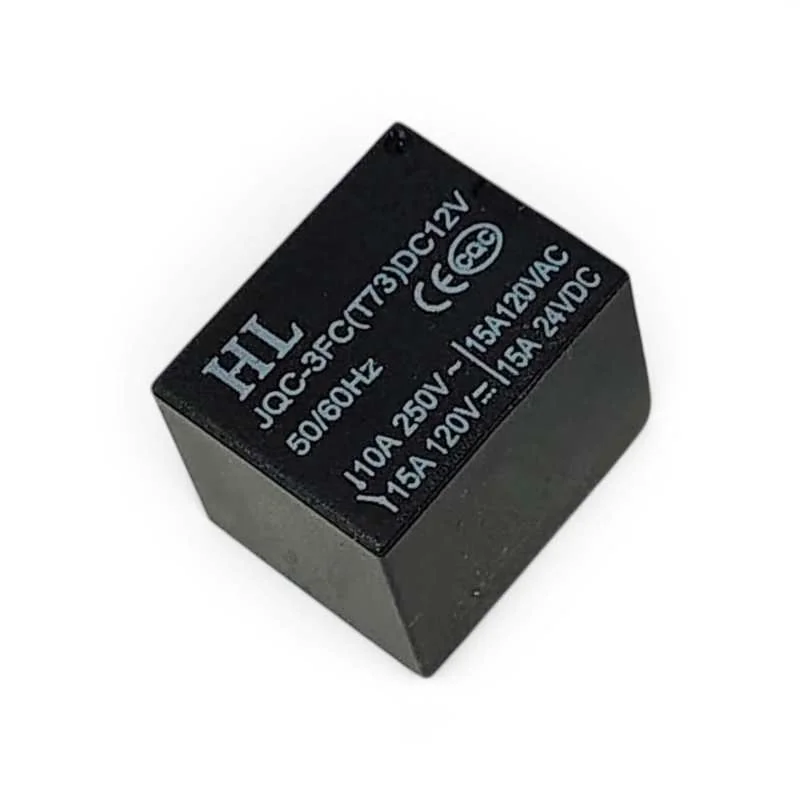
5 Pin Mini SPDT Relay 12V 10A 250V PCB Mount Electromagnetic Relay
[Relay Module, Relays] 12V PCB Mount Sugar Cube SPDT Relay – 5 Pin 10A The 12V PCB Mount Sugar Cube SPDT Relay is a compact Single Pole Double Throw (SPDT) electromagnetic relay designed for switching AC and DC electrical loads using a microcontroller, sensor, automation circuit, or other low-power control system. Its compact PCB-mount design makes it suitable for DIY electronics, home automation, security systems, switching circuits, motor control, lighting control, and embedded applications. The relay features a 12V DC coil and a 5-pin SPDT configuration consisting of two coil terminals, COM (Common), NO (Normally Open), and NC (Normally Closed) contacts. When the coil is energized, the internal contact switches between the NC and NO terminals. With contact ratings of up to 10A at 250V AC, 10A at 125V AC, 12A at 120V DC, and 10A at 28V DC, this relay is suitable for a wide range of electrical switching applications. ⭐ Key Features SPDT (Single Pole Double Throw) relay 12V DC coil Compact Sugar Cube design 5-pin configuration PCB mounting type 10A @ 250V AC contact rating 10A @ 125V AC contact rating 12A @ 120V DC contact rating 10A @ 28V DC contact rating Coil resistance: approximately 270Ω Approximately 45mA nominal coil current 50/60Hz frequency specification Fast switching response Suitable for microcontroller and sensor-controlled switching Ideal for automation and control applications 📋 Technical Specifications Product Type: PCB Mount Relay Relay Type: SPDT (Single Pole Double Throw) Contact Configuration: 1 Form C Number of Pins: 5 Coil Voltage: 12V DC Trigger Voltage: 12V DC Coil Resistance: 270Ω Nominal Coil Current: Approximately 45mA Frequency: 50/60Hz Maximum AC Load: 10A @ 250V AC Maximum AC Load: 10A @ 125V AC Maximum DC Load: 12A @ 120V DC Maximum DC Load: 10A @ 28V DC Operating Time: 10ms Release Time: 5ms Mounting Type: PCB Mount Contact Terminals: COM / NO / NC Coil Terminals: Coil End 1 / Coil End 2 🔌 Pin Configuration Coil End 1: One terminal of the 12V DC relay coil Coil End 2: Other terminal of the 12V DC relay coil COM: Common switching contact NO: Normally Open contact NC: Normally Closed contact When the relay coil is not energized, COM is connected to NC. When the 12V DC coil is energized, COM switches from NC to NO. 🛠️ How It Works The relay uses an electromagnetic coil to mechanically switch an electrical circuit. Applying 12V DC to the coil energizes the relay and changes the contact position. A load connected between COM and NC remains connected when the relay is inactive. A load connected between COM and NO remains disconnected until the relay coil is energized. This allows a low-power control circuit such as an Arduino, microcontroller, sensor, timer, or automation controller to control a higher-current AC or DC load. 🔧 Applications Arduino Projects Microcontroller Projects Sensor-Controlled Switching Home Automation Security Systems Lighting Control Fan Control Motor Control Pump Control Power Supply Switching Industrial Control Systems Embedded Electronics DIY Electronics Projects 📦 Package Includes 1 × 12V PCB Mount Sugar Cube SPDT Relay – 5 Pin 10A ⚠️ Precautions Use a suitable 12V DC supply for the relay coil. Do not exceed the specified contact voltage and current ratings. Check the COM, NO, NC, and coil terminals before wiring. Use suitable flyback protection when driving the relay coil from sensitive electronic circuits. Use appropriate suppression/protection components for inductive loads such as motors, solenoids, and coils. Provide sufficient PCB insulation and clearance when switching mains voltage. Disconnect power before changing or modifying wiring. Do not touch exposed mains-voltage terminals during operation.
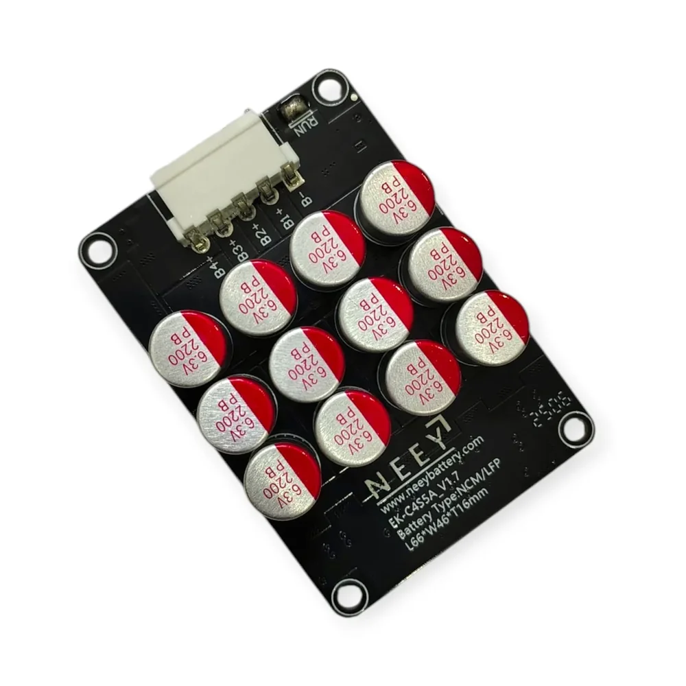
4S 5A Active Balancer Equalizer Board for LiFePO4/Li-ion
[Lithium Battery Protection Board] 4S 5A Active Balancer Equalizer Board for LiFePO4/Li-ion Software active equalization specification Number of battery pack strings – 4S Balance current ≤5A Balance mode – Active equilibrium working temperature -20°C~60°C The 4S5A Active Balancer (NEEY) is a battery management solution designed for 4 series lithium-based battery packs. It supports 5A of current per cell for active balancing, which ensures that all cells in the battery pack remain at a balanced voltage level. Active balancing redistributes energy from cells with higher voltage to those with lower voltage, optimizing the overall performance and efficiency of the battery. This helps prevent individual cells from becoming overcharged or discharged excessively, extending the lifespan and enhancing the safety of the battery pack. The NEEY model delivers reliable performance in energy storage systems, electric vehicles, and other high-demand lithium battery applications. Applicable battery type : NCM/LFP Teemary Lithium/Lithium Iron Single voltage working range: NCM/LFP version 3.0V-4.2V Balance method : Detect the nearby voltage difference is greater than 0.1V totrigger the start of balanced the adjacent battery voltage difference is less than 003V to stop working Balance current: 0.2V Adjacent voltage difference 0.1V, Balance current: 054-0.74, Adjacent voltage difference 0.2V. Balanced current: 2A LED indicator : 1. When the equalization light is on the equalization work is turned on, 2. The equalization light goes out the equalization circuit sleeps Operating Temperature Range: -20° to 60° The smaller the differential voltage, the smaller the balance current. Package Include: 1x 4S 5A Active Balancer Equalizer Board for LiFePO4/Li-ion 1x Cable
 Out of stock
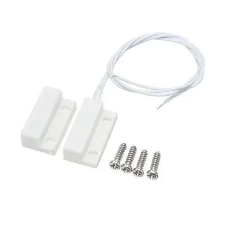
MC-38 Wired Door Window Sensor Magnetic Switch Home Alarm System
[Magnetic Sensor] If you want to Apply Extra Security for your house then this Magnetic Switch is needed for you. This magnetic switch is used for triggering an alarm or ON/OFF light inside a cupboard sliding door In-home alarm systems you need many sensors like proximity sensors, Heat detection sensors, and Magnetic door sensors to determine the safety status of the home. In these sensors door sensors are important as these determine whether the gate is open or closed. This is an MC-38 Door Window Sensor Magnetic Switch Home Alarm System Normally Closed type which you can install on your door and use it with your home alarm system. It is very easy to install and conceal and can be easily used in places like your home, office, and hotels. Connection Diagram of MC-38 With Arduino: Features : Easy to install Strong concealment The magnetic sensor alarm, controls the switch of the circuit via the built-in magnet Alarm when someone intrudes into your places Can be used in places like apartments, hotels, offices, etc. Ideal for residential or commercial use. Designed to do embedded in the door or window frame. Package Includes : 1 x MC-38 Wired Door Window Sensor Magnetic Switch Home Alarm System. 4 x M5 screws for fitting.
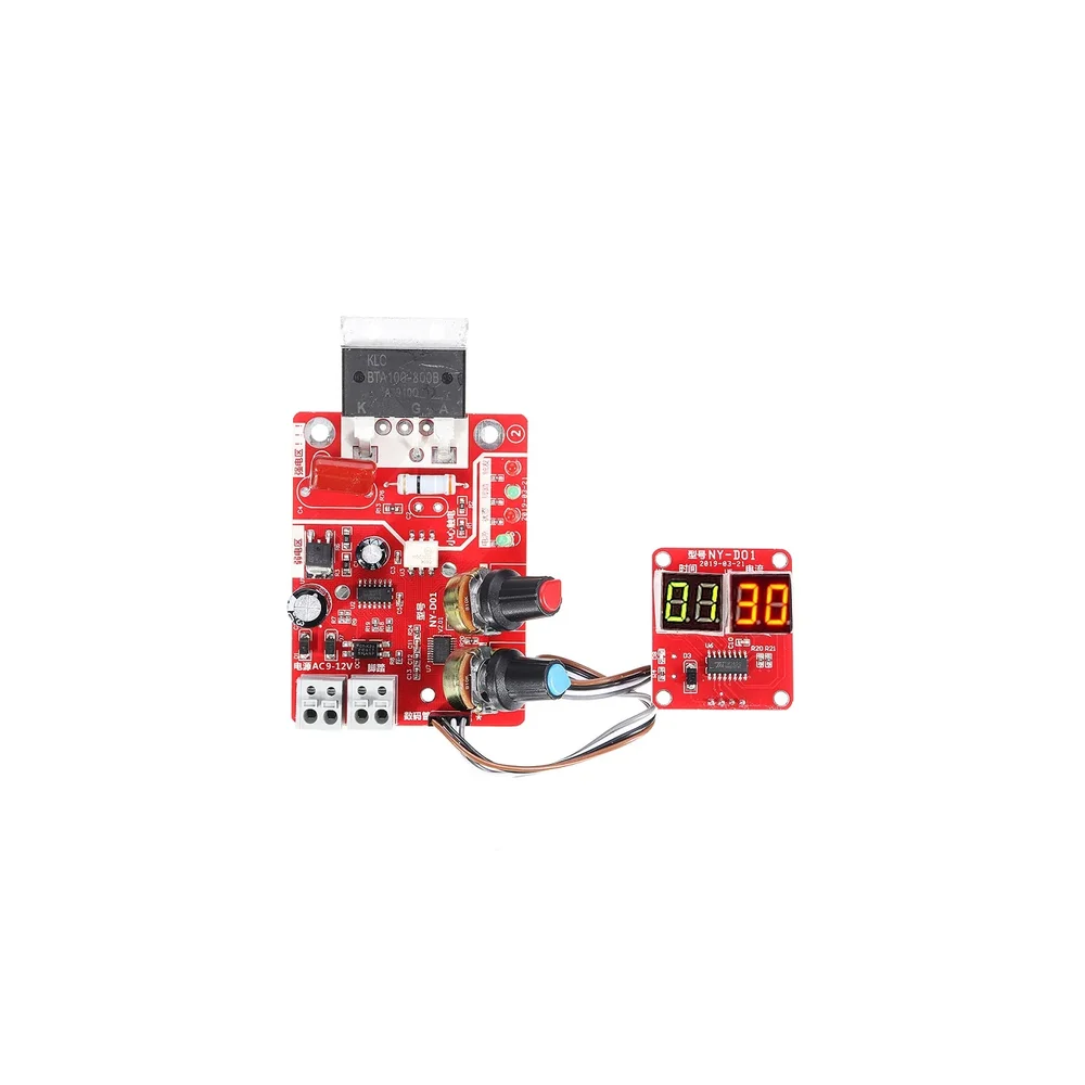
NY-D01 100A Digital Display Spot Welding Controller Board
[Spot Welding Parts] The principle of silicon-controlled phase shifting triggering is adopted to adjust the time and the current to achieve welding. With a digital display, you can directly see the time and current. Optocoupler isolates the strong and weak electricity, making the operation safer. Using a high-precision single potentiometer to ensure reliable and convenient input. The design of a reliable zero-crossing detection circuit ensures the SCR phase shift accuracy. Made of high-quality PCB, the control board is long-lasting. The module is 8cm long, 6cm wide, and 2cm high. It is developed for DIY or simple resistance welding. Features: 1 The use of STM8 industrial control center microcontroller. 2 Strong and weak electricity through optocoupler insulation, safe operation. 3 The power line and foot switch line adopts the bolt the quick connect terminal, more convenient and reliable. 4 Input time, current using a high-precision simple potentiometer, to ensure reliable, convenient input 5 On-board power supply, state, foot, trigger indicator, work status clearly visible. 6 The design of reliable zero-crossing detection circuit to ensure that the SCR phase shift accuracy. 7 The controller is compatible with 100A scr. 8 Digital control interface, you can display the current time and current settings. 9 Input time of 1-50, cycle unit (1 cycles is 20 ms), current input (30-99%), Material Plastic+Metal Current Input 30-99% Microcontroller. STM8 Time input 1-50 Shipping Weight 0.12 kg Shipping Dimensions 8 × 6 × 2 cm Package Includes: 1 x NY-D01 100A Digital Display Spot Welding Controller Board
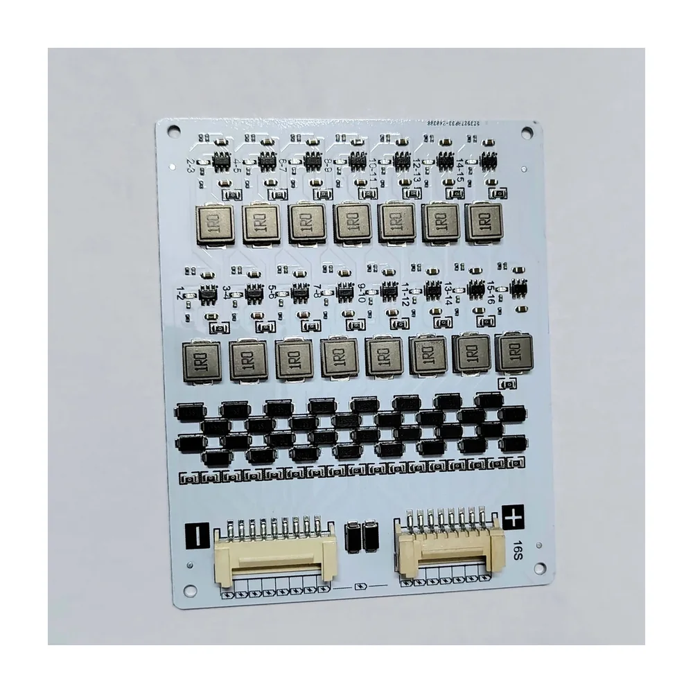
16s 2Amps Active Balancer Equalizer for NCM/LFP Battery
[Lithium Battery Protection Board] The 16S2A Active Balancer (NEEY) is a battery management solution designed for 16 series lithium-based battery packs. It supports 2A of current per cell for active balancing, which helps ensure that all cells in the battery pack are charged to the same voltage level. Active balancing optimizes battery performance by redistributing energy from higher-voltage cells to lower-voltage cells, thus improving the overall efficiency and lifespan of the battery pack. This balancer helps to prevent overcharging or deep discharging of individual cells, ensuring a safer and more reliable operation. The NEEY designation indicates the specific brand or model, offering efficient and effective cell balancing for applications such as energy storage systems, electric vehicles, and other lithium-based power solutions. Balancer Specification – Suitable – 16S 48volt Applicable battery type : NCM/LFP Teemary Lithium/Lithium Iron Single voltage working range: NCM/LFP version 3.0V-4.2V Balance method : Detect the nearby voltage difference is greater than 0.1V totrigger the start of balanced the adjacent battery voltage difference is less than 003V to stop working Balance current: 0.2V Adjacent voltage difference 0.1V, Balance current: 054-0.74, Adjacent voltage difference 0.2V. Balance current: 2A LED indicator : 1. When the equalization light is on the equalization work is turned on, 2. The equalization light goes out the equalization circuit sleeps Operating Temperature Range: -20° to 60° The smaller the differential voltage, the smaller the balance current. package Include – 1. Balancer Unit 2. Balancer Wires
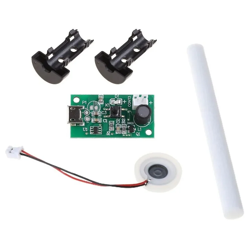
DC5V Humidifier USB Spray Module DIY Incubation Experiment Equipm 108KHz(mist maker)
[Ultrasonic Sensor] Description This DC Ultrasonic Humidifiers Power Circuit Board with Atomizing Chip Moisture Film Humidification atomization machine consists of an atomization plate tablet with a diameter of 20mm. This Ultrasonic Humidifier Piezoelectric Transmitter module works on the principle of cavitation produced by sound waves. Just provide the DC 3V to 5V power supply it will turn into a mini ultrasonic atomizer. As sound waves contain compression and rarefaction. Due to extremely rapid movement, water droplets can no longer sustain their liquid state and get converted into vapor immediately. This vibration is produced by a piezoelectric filament. Tags, USB Humidifier Atomization Driver Board PCB Circuit Board 5V Spray Incubation, Tags, OEM/ODM Available Mini Humidifier USB spray module humidifier pcb circuit board for DIY kit Incubation Experiment Equipment, USB Humidifier Atomization Driver Board PCB Circuit Board 5V Spray Incubation, 5V DIY Ultrasonic Piezoelectric Humidifier Moisture Atomizing Chip Mist maker circuit board. Features Come with a driver Power-ON trigger work 108KHz high-frequency oscillator Micron level aperture The glazed surface of the atomized sheet Features/Specs: Product Name: 108KHz 20mm USB Humidifier Work Voltage: DC 4.5V~5.0V Work Power:2W Work Frequency:108KHz(+/-3KHz) Power Type: Female USB Socket Diameter without rubber ring:16mm Diameter with rubber ring:20mm Spray Diameter:5um Spray Hole:740 holes Spray speed:50ml/h Work Temperature:0℃ ~ 85℃ Work Humidity:10%~90%RH Driver Size:35*19*15mm Length: 35 mm Width: 19 mm Height: 15 mm Weight: 10 gm Application: Humidifier | mist maker Beauty care for facial massager Medical liquid atomizing Equipment Package Includes: 1pc x Humidifier Driver Bord 1pc x 16mm Atomizer Plate 1pc x Cotton Stick Stand 1pc x Cotton Stick
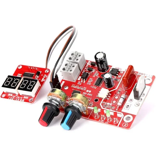
NY-D01 40A Digital Display Spot Welding Controller Board
[Spot Welding Parts] This is a NY-D01 40A Digital Display Spot Welding Controller Board. The principle of silicon controlled phase shifting triggering is adopted to adjust the time and the current to achieve welding. With a digital display, you can directly see the time and current. Optocoupler isolates the strong and weak electricity, making the operation safer. Using a high-precision single potentiometer to ensure reliable and convenient input. The design of a reliable zero-crossing detection circuit ensures the SCR phase shift accuracy. Made of high-quality PCB, the control board is long-lasting. The module is 8cm long, 6cm wide and 2cm high. It is developed for DIY or simple resistance welding. Connection Diagram: Features: 1 The use of STM8 industrial control centre microcontroller. 2 Strong and weak electricity through optocoupler insulation, safe operation. 3 The power line and footswitch line adopts the bolt the quick connect terminal, more convenient and reliable. 4 Input time, current using a high-precision simple potentiometer, to ensure reliable, convenient input 5 On-board power supply, state, foot, trigger indicator, work status clearly visible. 6 The design of a reliable zero-crossing detection circuit to ensure that the SCR phase shift accuracy. 7 The controller is compatible with 40A SCR. 8 Digital control interface, you can display the current time and current settings. 9 Input time of 1-50, cycle unit (1 cycles is 20 ms), current input (30-99%), Package Includes: 1 x NY-D01 40A Digital Display Spot Welding Controller Board
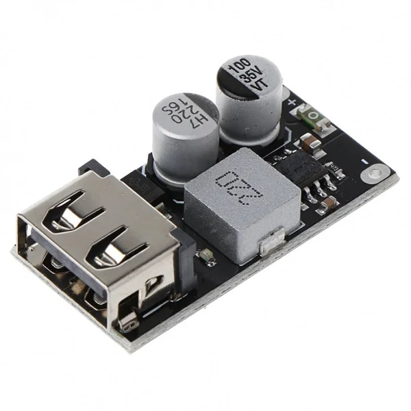
USB QC3.0 QC2.0 DC to DC Buck Converter Charging Module Fast Quick Charger
[Step Down Buck Converter] This module accepts a 6-24V Input and supports USB QC3 Charging on the output. It takes care of regulating the signals on the USB Data transer lines and offers fast charging when a compatible device is connected. Great for adding USB charging in your next project. Supports: QC2.0, QC3.0, MTK PE1.1/2.0, FOR Apple, FOR Samsung AFC,FOR Huawei FCP, FOR Spreadtrum SFCP Input voltage: DC 6~30V Output voltage: default 5V, adjust range 3~12V according to fast charging protocol Output capacity: single-port rated current 2.4A, Rated power 24W Protection measures: Output overvoltage protection, limit the output voltage does not exceed 13V (in the case of chip failure); input with a fuse. This mini DC-DC step-down voltage converter module supports 6-24V voltage input and 5V 3A output with input polarity reverse protection and output overvoltage protection, short circuit protection. It adopts synchronous rectification technology to ensure ultra-high power conversion up to 97.5% to take full use of your input power. On-board female type A USB port with identification circuit perfectly fit for smartphones as well as it can be useful to power or recharge any electronic gadget which required 5V input power up to 3A Features: Non-isolated buck module (BUCK) synchronous rectification Maximum Output Current: 3A MAX Conversion efficiency: can up to 97.5% (6.5V step down to 5V 0.7A) (after short reverse protection and fuses test value) Switch frequency: 500KHz Output Ripple: 10mV around (12V to 5V3A) 20M bandwidth Output indicator: The output voltage indicator is red Operating temperature: Industrial grade (-40 to + 85 ) (the higher the ambient temperature, the lower the output power) Output overvoltage protection: Yes, input 1.5A fuse, output 5V have 300W TVS tube clamp protection. Flat copper inductor, improve conversion efficiency With output overvoltage protection. There is a 1.5A fuse, output 5V have 300W TVS tube protect your USB device High-quality USB port Output voltage indicator (RED) Small size, Compact Size Input with reverse polarity protection diode, will not damage when input connect incorrectly Ultra-low static current, 0.85 mA only. Do not need to add switch when connected to the car battery, can be connected to car cigarette lighter cable or ACC power supply cable Ultra-small size, 26.4 (L) * 15 (W) * 7.4 (H) mm Input voltage range: 6V-32V Output voltage: default 5V, automatically adjust between 3-12V after triggering fast charge Output power: up to 24W (5V/3.4A, 9V/2.5A, 12V/2A, etc.) Output voltage cable compensation function Conversion efficiency: 90%-97% Support multiple fast charging protocols Input overvoltage and undervoltage protection Input overcurrent protection Output overcurrent, short circuit protection Machine over temperature protection Support fast charge agreement Support DCP protocol, BC1.2, Apple, Samsung protocol Support Huawei Fast Charge Protocol FCP/SCP Support Huawei Fast Charge Protocol AFC Support Spreadtrum Fast Charge Protocol SFCP · Support Qualcomm QC2.0 and 3.0 Support MTK PE1.1/PE2.0 Precautions: please enhance heat dissipation when fully used for load output(i.e. 5V@3A with 24V Input). For the ideal case (i.e. 5V@2A output with 12V Input) it does not need to enhance heat dissipation. Applications: Solar panel to mobile phone charging Car charging retrofit Driving recorder power supply Home power supply, smart plug modification Fast charge adapter Package Includes: 1 x USB Step Down DC-DC Converter Module
 Out of stock
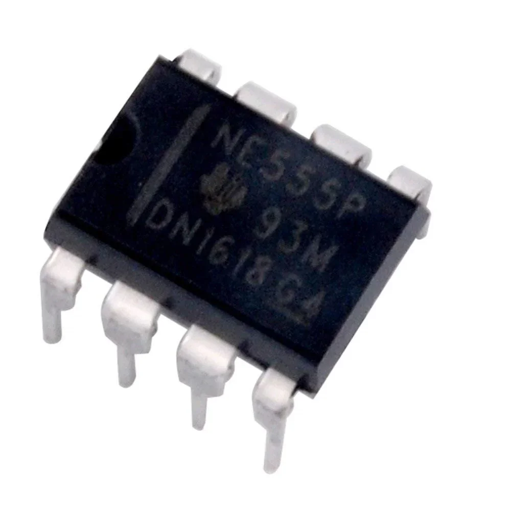
NE 555 P PDIP-8 Timer IC
[Timer,Clock,Counter ICs] The NE 555 P timer IC is a precision timing circuit capable of producing accurate time delays or oscillation. In the time-delay or monostable mode of operation, the timed interval is controlled by a single external resistor and capacitor network. In the as table mode of operation, the frequency and duty cycle can be controlled independently with two external resistors and a single external capacitor. The threshold and trigger levels normally are two-thirds and one-third, respectively, of VCC. These levels can be altered by the use of the control voltage terminal. When the trigger input falls below the trigger level, the flip-flop is set, and the output goes high. If the trigger input is above the trigger level and the threshold input is above the threshold level, the flip-flop is reset and the output is low. Features: Timing from microseconds to hours A stable or monostable operation Adjustable duty cycle TTL compatible output can sink or source up to 200mA Applications: Clock & Timing, Consumer Electronics, Aerospace, Defence, Military, Embedded Design & Development Package Includes: 1 x NE 555 P PDIP-8 Timer IC
 Out of stock
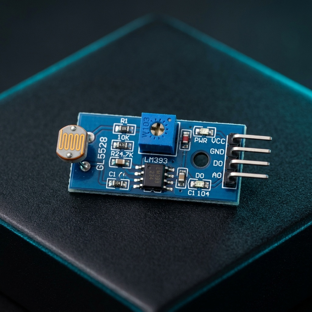
Digital LDR Module
[Light Sensors] The Digital LDR Module is used to detect the presence of light / measuring the intensity of light. The output of the module goes high in the presence of light and it becomes low in the absence of light. The sensitivity of signal detection can be adjusted using the potentiometer. Use it to detect the light brightness in your environment and decide to switch OFF or ON light? Or maybe to adjust the brightness of the LED of your house? You can adjust the threshold (sensitivity) of the digital output by tuning the onboard variable resistor (potentiometer). Simple usage as it is the digital output, so you will know is the light present and decide what to do with it. It comes with an M3 mounting hole for ease of attaching it to an object. Onboard, it provides an LDR, high sensitivity and commonly being used for light detection. The module comes with a power LED and a status LED as an indicator. LDR Module Photosensitive resistor module most sensitive to environmental light intensity is generally used to detect the ambient brightness and light intensity. Features – LM393 based design. Can detect ambient brightness and light intensity. Adjustable sensitivity (via blue digital potentiometer adjustment). Output Digital – 0V to 5V, Adjustable trigger level from preset. LEDs indicating output and power. Operating Voltage: 3.3V to 5V DC. Operating Current: 15ma. How it works 1. Module light conditions or light intensity reach the set threshold, DO port output high when the external ambient light intensity exceeds a set threshold, the module D0 output low; 2. Digital output D0 directly connected to the MCU, and detect high or low TTL, thereby detecting ambient light intensity changes; 3. Digital output module DO can directly drive the relay module, which can be composed of a photoelectric switch. Pin details VCC ↔ 3.3V to 5V DC. GND ↔ Ground. DO ↔ Digital Output.
 Out of stock
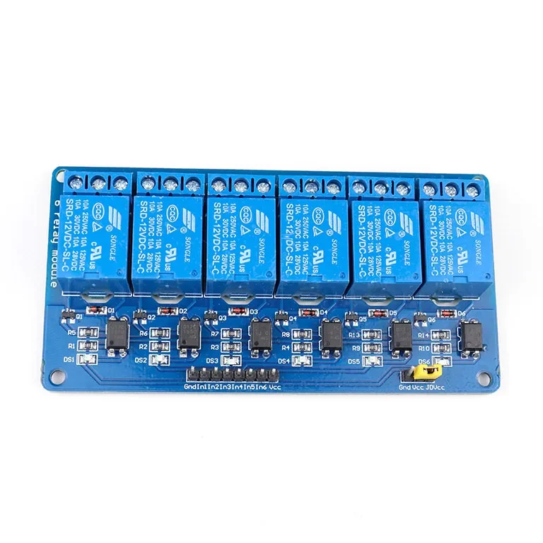
12V 6 Channel with Light Coupling Relay Module
[Relay Module] This 6 Road/Channel Relay Module (with light coupling) 12V module meets the safety standard as control areas and load area have the isolation groove. Optical coupling isolation module. The triggering of the 6 Road/Channel Relay Module is reliable, more stable. The double FR–4 circuit board design, high-end SMT process. It has power and relay operation instructions. Relays terminals (C, NC, NO) are accessible through screw terminals which makes wiring up the board very easy. The inputs of the 8 Channel 12V Relay Module are isolated to protect any delicate control circuitry. A wide range of microcontrollers such as Arduino, AVR, PIC, ARM and so on can control it. The use of such high-voltage relay eliminates the risk of heating up of the relay as electromechanical relay limit the current consumption in accordance with a voltage rating. Module interface: The positive (according to the relay voltage VCC: connect power supply) GND: connect power negative IN1: relay module (effective) high-level trigger signal trigger end IN2: relay module (effective) high-level trigger signal trigger end IN3: relay module (effective) high-level trigger signal trigger end IN4: relay module (effective) high-level trigger signal trigger end IN5: relay module (effective) high-level trigger signal trigger end IN6: relay module (effective) high-level trigger signal trigger end IN7: relay module (effective) high-level trigger signal trigger end IN8: relay module (effective) high-level trigger signal trigger end Meaning of High level and Low-level High-level trigger refers to using the anode voltage at the VCC connection way of a trigger and triggers the end when the trigger side has a positive voltage or to trigger voltage when the relay is off. Low-level trigger refers to using the negative voltage at the GND connection way of a trigger and triggers the end when the trigger side has 0 v low voltage or voltage to can trigger, the relay is off. Features : Equipped with high-current relay 10A@250VAC / 10A@30VDC It can control both AC and DC appliances such as Solenoids, Motors, lights, fans, etc High-quality screw terminals (Terminal Block) provided (C, NC, NO) for quick and easy connection A freewheeling diode to protect your microcontroller Input Signal Pin connected to Burg stick for easy accessibility LED status indicators to indicate the relay ON/OFF status Mounting holes provided Signal input with a high-level signal, the common and often start conduction; The relay can directly control all kinds of equipment and load; One often opened a normally closed contact; Blue KF301 terminal line more convenient. It is also able to control various appliances and other types of equipment with a large current. Red working status indicator lights are conducive to safe use. Widely used for all MCU control, industrial sector, PLC control, smart home control. Package Includes: 1 x 12V 6 Channel with Light Coupling Relay Module
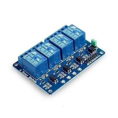
4 Channel Isolated 5V 10A Relay Module opto coupler For Arduino PIC AVR DSP ARM
[Relay Module] The 4 Channel Isolated 5V Relay Module is a reliable switching interface that enables low-voltage microcontrollers to safely control high-voltage and high-current electrical devices. Featuring four independent relays with opto-isolation, the module provides excellent electrical separation between the control circuitry and load side for enhanced safety and reliability. In addition, each relay can be individually controlled through dedicated input pins, allowing multiple devices to be switched independently. As a result, the module is ideal for home automation, industrial control systems, robotics, IoT projects, and appliance control applications. Because of its opto-coupler isolation design, the relay board helps protect sensitive microcontrollers from electrical noise and voltage spikes. Furthermore, onboard status LEDs provide clear indication of relay activation and power status. The module supports both AC and DC load switching, making it suitable for controlling lamps, fans, pumps, motors, solenoids, and various household appliances. Moreover, the high-quality relay contacts ensure reliable long-term operation under demanding conditions. This relay module is widely used in Arduino projects, Raspberry Pi automation systems, PLC control panels, industrial automation, smart home systems, and embedded electronics applications. 🔹 Key Features 4 independent relay channels Opto-isolated input design Supports high and low level triggering Compatible with Arduino, Raspberry Pi, ESP32, PIC, AVR, ARM, and PLC High-current relay contacts LED power and relay status indicators Electrical isolation between control and load circuits Suitable for AC and DC load switching Easy interfacing with microcontrollers Industrial-grade design 🔹 Technical Specifications Product Type: 4 Channel Relay Module Operating Voltage: 5V DC Number of Channels: 4 Relay Type: JQC3F-5VDC-C / SRD-05VDC-SL-C / FL-3FF-S-Z (Random) Contact Configuration: SPDT (NO, COM, NC) Maximum AC Load: 250V AC, 10A Maximum DC Load: 30V DC, 10A Trigger Voltage: Approx. 1V – 5V Isolation Method: Opto-Coupler Isolation Input Interface: Standard TTL Control Signal Trigger Mode: High-Level / Low-Level Trigger Status Indicators: Power LED and Relay LEDs Mounting Holes: Yes 🔹 Pin Configuration Control Side VCC – 5V Power Supply GND – Ground IN1 – Relay Channel 1 Control IN2 – Relay Channel 2 Control IN3 – Relay Channel 3 Control IN4 – Relay Channel 4 Control Relay Output Terminals For each channel: COM – Common Terminal NO – Normally Open Contact NC – Normally Closed Contact 🔹 Applications This relay module is suitable for: Arduino projects Raspberry Pi projects ESP32 projects Home automation systems Industrial automation PLC control systems Smart home devices Lighting control Motor and pump control Appliance switching IoT projects 🔹 Package Includes 1 × 4 Channel 5V 10A Opto-Isolated Relay Module
 Out of stock
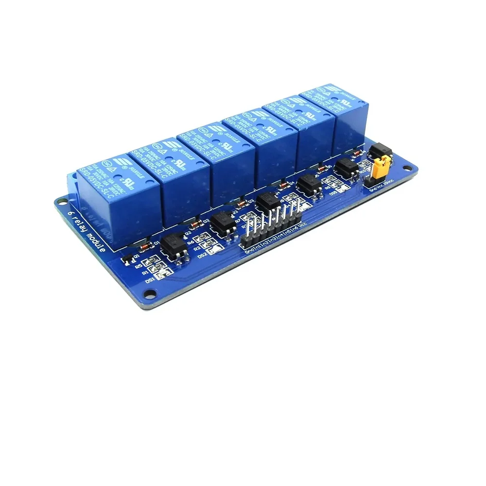
5V 6 Channel Low Level Relay Module with Light Coupling
[Relay Module] It is a 5V 6 Channel Low-Level Relay Module with Light Coupling. The relay normally open interface maximum load: AC 250V/10A, DC 30V/10A. With optocoupler isolation, strong drive capability, stable performance; trigger current 5mA, module working voltage: DC 5V. Each channel of the module can be triggered by a jumper to set a high level or a low level. Fault-tolerant design, even if the control line is disconnected, the relay will not move. With status indicator: power (green), 6-channel relay status indicator (red). All module size interfaces can be directly connected through the terminal block, which is convenient and practical. Features: 6-way relay output module contact capacity is 10A 250V. input IN1, IN2, IN3, IN4, IN5, IN6 signal, a low level is effective. Using single-chip design, reliable performance, strong anti-interference, no false triggering, superior performance. The trigger terminal has optocoupler isolation, the independent external power supply can trigger completely isolated. Each relay has an activity indicator light. With 4 fixed bolt holes, easy installation. Support all SCM control. It is applicable to the industrial sector, PLC control and home intelligent control. Package Includes: 1 x 5V 6 Channel Low-Level Relay Module with Light Coupling.
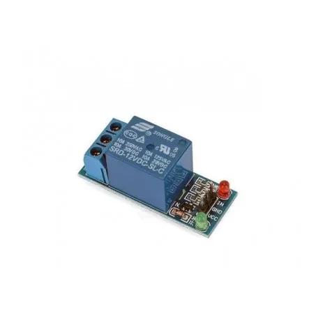
1 Channel 12V Relay Module without Optocoupler
[Relay Module] 🔌 12V 1 Channel 7A Relay Module for Arduino, Raspberry Pi & Microcontrollers 12V Trigger • 7A Relay • Compact Design • Ideal for Automation & DIY Projects The 12V 1 Channel 7A Relay Module is a compact and reliable relay board designed to control AC and DC loads using low-voltage control signals from microcontrollers and development boards. Operating on a 12V DC trigger voltage, it can be directly interfaced with Arduino, Raspberry Pi, ESP32, ESP8266, AVR, PIC, 8051, ARM, and other embedded systems. The module is equipped with a high-quality 7A electromagnetic relay capable of switching 250V AC or 30V DC loads. It features LED indicators for power and relay status, making debugging and operation simple. Standard header pins allow easy connection to development boards, while screw terminals provide secure wiring for external loads. This relay module is ideal for home automation, industrial control, IoT projects, robotics, lighting control, motor switching, and various DIY electronics applications. ⭐ Features Single-channel 12V relay module High-quality 7A electromagnetic relay Compatible with Arduino, Raspberry Pi, ESP32, AVR, PIC, ARM and more 12V DC trigger input LED power and relay status indicators Standard header pin interface Screw terminal output connections Compact PCB design Reliable and stable operation Easy installation 📋 Technical Specifications Product Type: Relay Module Relay Channels: 1 Operating Voltage: 12V DC Trigger Voltage: 12V DC Trigger Current: Approx. 20mA Maximum Switching Voltage (AC): 250V AC Maximum Switching Current (AC): 7A Maximum Switching Voltage (DC): 30V DC Maximum Switching Current (DC): 7A Relay Contact Type: SPDT (NO / NC / COM) Connection Type: Screw Terminal + Header Pins Operating Temperature: -40°C to +85°C Board Dimensions: Approx. 48 × 29 × 17 mm (May vary slightly by manufacturer) Weight: Approx. 15g 🔧 Applications Suitable for: Arduino Projects Raspberry Pi Projects ESP32 & ESP8266 Projects Home Automation Industrial Automation Smart Switches Lighting Control Fan Control Pump Control Small Motor Switching Security Systems Robotics IoT Projects DIY Electronics 📦 Package Includes 1 × 12V 1 Channel 7A Relay Module ⚠️ Note This module is intended for switching high-voltage AC/DC loads. Always disconnect power before wiring. Product images are for illustrative purposes only. The actual product may vary slightly depending on the manufacturing batch.
 Out of stock
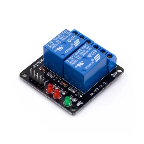
2 Channel 5V Relay Module
[Relay Module] This is a 2 Channel 5V Relay module, be able to control various appliances, and other equipment with large current. It can be controlled directly by Microcontroller (8051, AVR, PIC, DSP, ARM, ARM, MSP430, TTL logic).5V 2-Channel Relay interface board and each one needs 15-20mA Driver Current Equipped with high-current relay, AC250V 10A; DC30V 10A Standard interface that can be controlled directly by microcontroller (8051, AVR, PIC, DSP, ARM, ARM, MSP430, TTL logic) Indication LEDs for Relay output status. Features: The module using Single relay control. AC voltage 250V, AC current 10A, maximum DC voltage 30V DC current maximum 10A. Power indicator (green), Two ways of relay status indicator light (red). Using 8550 transistor-driven, strong driving ability. Has the fixed bolt hole and easy installation. Package Includes: 1 x 5V 2 Channel Relay Module. Specifications :- Operating Voltage (VDC) 2.5 ~ 5.5 Trigger Voltage (VDC) 5 Trigger Current (mA) 20 Switching Voltage (VAC) 250@10A Switching Voltage (VDC) 30@10A Operating Temperature (C) -40 to 85 Opt. Relative Humidity(RH) 20% 85% Storage condition () 65 to 125 Length (mm) 43 Width (mm) 43 Height (mm) 17 Weight (gm) 25
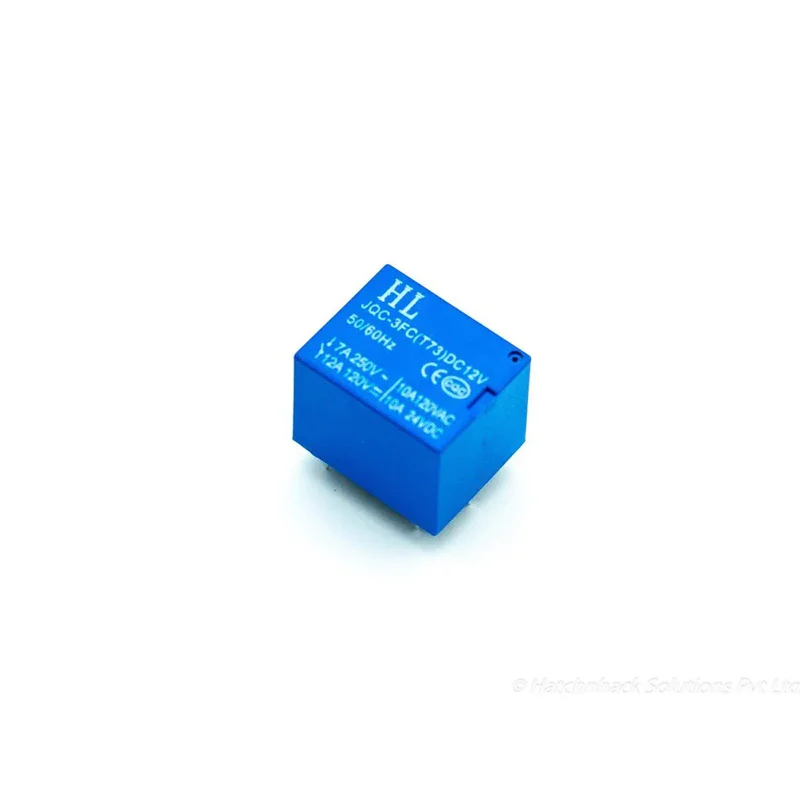
12V PCB Mount Sugar Cube SPDT Relay – 5 Pin 7A
[Relays] 12V PCB Mount Sugar Cube SPDT Relay – 5 Pin 7A The 12V PCB Mount Sugar Cube SPDT Relay is a compact Single Pole Double Throw (SPDT) electromagnetic relay designed for switching AC or DC loads using a microcontroller, sensor, control circuit, or other low-power trigger source. Despite its small size, this relay can be used to control loads up to 7A at 250V AC according to the provided specifications. The relay operates with a 12V DC coil and has a coil resistance of approximately 270Ω, with a nominal coil current of around 45mA. Its compact PCB-mount design makes it suitable for use in automation systems, switching circuits, security systems, control panels, DIY electronics, and embedded projects. The relay features 5 pins: two coil terminals, COM (Common), NO (Normally Open), and NC (Normally Closed). The COM terminal is switched between NO and NC when the relay coil is energized or de-energized. ⭐ Key Features SPDT (Single Pole Double Throw) relay 12V DC coil Compact Sugar Cube design PCB mounting type 5-pin configuration Coil resistance: approximately 270Ω Nominal coil current: approximately 45mA Suitable for switching AC and DC loads Maximum AC load: 7A @ 250/125V AC Compact and easy to install Suitable for microcontroller and sensor-controlled switching Useful for automation and control applications 📋 Technical Specifications Product Type: PCB Mount Relay Relay Type: SPDT Contact Configuration: 1 Form C Number of Pins: 5 Coil Voltage: 12V DC Trigger Voltage: 12V DC Coil Resistance: 270Ω Trigger / Nominal Coil Current: Approximately 45mA Maximum AC Load Current: 7A @ 250/125V AC Maximum DC Load Current: 10A @ 24/120V DC as specified Operating Time: 10ms Release Time: 5ms Mounting Type: PCB Mount Contact Terminals: COM / NO / NC Coil Terminals: Coil End 1 / Coil End 2 🔌 Pin Configuration Coil End 1: One terminal of the 12V DC relay coil Coil End 2: Other terminal of the 12V DC relay coil COM: Common contact connected to the load circuit NO: Normally Open contact NC: Normally Closed contact When the relay coil is not energized, COM is connected to NC. When the 12V DC coil is energized, the internal contact switches from NC to NO. 🛠️ How It Works Connect the relay coil terminals to a suitable 12V DC control supply. When the coil is energized, the internal contact changes state and switches the connected load between the NC and NO terminals. For an NC connection, the load can remain connected before the relay is triggered. For an NO connection, the load remains disconnected until the relay coil is energized. The relay allows a low-power control circuit such as a microcontroller, sensor, timer, or automation controller to control a higher-current electrical load. 🔧 Applications Microcontroller Projects Arduino Projects Sensor-Controlled Switching Home Automation Security Systems Switching Circuits Motor Control Lighting Control Fan Control PCB Control Boards Embedded Electronics Industrial Control Systems DIY Electronics Projects 📦 Package Includes 1 × 12V PCB Mount Sugar Cube SPDT Relay – 5 Pin ⚠️ Precautions Use a 12V DC supply for the relay coil. Do not exceed the specified contact voltage and current ratings. Ensure correct identification of COM, NO, NC, and coil terminals before wiring. Use suitable protection circuitry when driving the relay coil from sensitive electronic circuits. For inductive loads such as motors and solenoids, use appropriate suppression/protection components. Ensure proper PCB insulation and clearance when switching mains voltage. Disconnect power before changing or modifying wiring. Do not touch exposed mains-voltage terminals during operation. ally Open) then the load remains OFF before trigger. These relays are usually used in home automation, switching circuits, securi
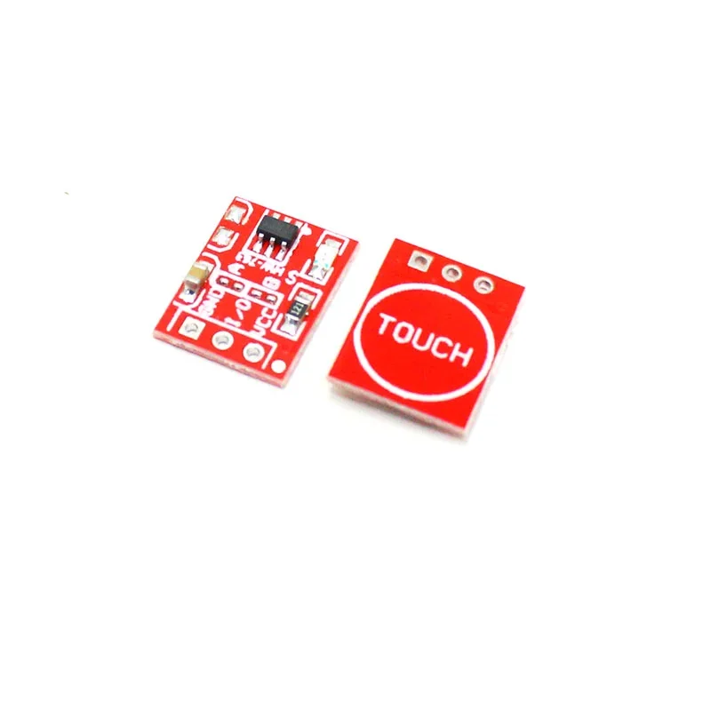
TTP223 Touch Key Module
[Sensors, Touch Sensors] The TTP223 Touch Key Module is based on a touch-sensing IC (TTP223) capacitive touch switch module. A capacitive touch sensor module based on the dedicated TTP223 touch sensor IC. The module provides a single integrated touch sensing area of 11 x 10.5mm with a sensor range of ~5mm. An onboard LED will give a visual indication of when the sensor is triggered. When triggered the output of the module will switch from its idle low state to high (default operation). Solder jumpers allow for reconfiguring its mode of operation to be either active low or toggle output. TTP223 Capacitive Touch Sensor Module. The TTP223 is a touchpad detector IC replicating a single tactile button. The TTP223 is a touchpad detector IC replicating a single tactile button. This touch detection IC is designed for replacing traditional direct button key with diverse pad size. Trigger-setting mode: (1- > Short ; 0- > No Short) AB=00: No-lock High TTL level output; AB=01: Self-lock High TTL level output; AB=10: No-lock Low TTL level output; AB=11: Self-lock Low TTL level output; Connection Diagram: Features : Supports momentary or latching/toggle modes. Supports Active High or Active Low output signal modes. Dimensions : 15mm x 11mm. Input Voltage : 2 Volt – 5.5 Volts DC. The response time max ~ 60mS in fast mode, ~220mS at low power mode @VDD=3V. Sensitivity can adjust by the capacitance(0~50pF). Have two kinds of sampling length by pad option(SLRFTB pin). Stable touching detection of the human body for replacing traditional direct switch key. Provides Fast mode and Low Power mode selection by pad option(LPMB pin). Provides direct mode、toggle mode by pad option(TOG pin). Open drain mode by bonding option, OPDO pin is open drain output, Q pin is CMOS output. All output modes can be selected active high or active low by pad option(AHLB pin). Have the maximum on time 100sec by pad option(MOTB pin). Have external power-on reset pin(RST pin). After power-on have about 0.5sec stable-time, during the time do not touch the keypad, and the function is disabled. Auto calibration. Re-calibration period is about 4.0 sec when the key has not be touched. Package Includes : 1 x TTP223 TOUCH KEY MODULE
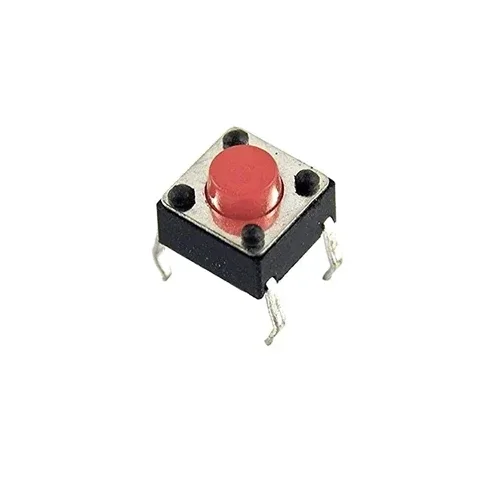
6×6×5mm Tactile Push Button Switch – Through-Hole Red
[Mechanical Switches] 6×6×5mm Tactile Push Button Switch – Through-Hole The 6×6×5mm Tactile Push Button Switch is a compact momentary push-button switch widely used as a standard input button in electronic circuits, PCB projects, Arduino projects, DIY electronics, consumer electronics, and control panels. The switch is normally open and temporarily closes the circuit when the button is pressed. Its compact 6×6mm body with 5mm height makes it suitable for space-constrained PCB designs. The through-hole construction allows secure PCB mounting and can also be used with solderless breadboards for prototyping. The switch provides tactile feedback during operation and is designed for repeated switching applications. It is suitable for applications including telecommunications, consumer electronics, audio/visual equipment, testing and instrumentation, computers, and peripheral devices. ⭐ Key Features 6×6×5mm compact size Momentary tactile push-button switch Normally Open (NO) contact Through-hole PCB design Suitable for breadboard prototyping Round shaft/button design Strong tactile feedback Long operating life of up to 300,000 cycles as specified Compact and lightweight Good electrical conductivity Suitable for electronic products and household appliances Designed for reliable repeated operation 📋 Technical Specifications Product Type: Tactile Push Button Switch Dimensions: 6 × 6 × 5mm Switch Type: Momentary Tactile Push Button Contact Type: Normally Open (NO) Mounting Type: Through Hole Button/Shaft Shape: Round Operation: Momentary Color: Red Operating Life: Up to 300,000 cycles Contact Technology: Dome Contact Application: PCB / Electronic Circuits Breadboard Compatible: Yes Construction: Compact and Lightweight 🔌 How It Works The switch contacts remain open when the button is not pressed. Pressing the button temporarily closes the contacts and completes the electrical circuit. When the button is released, the contacts return to their normally open state. This makes the switch suitable for reset buttons, menu controls, user inputs, trigger buttons, and other momentary switching applications. 🔧 Applications Arduino Projects Microcontroller Projects PCB Prototyping DIY Electronics Consumer Electronics Telecommunications Equipment Audio / Visual Equipment Computer Peripherals Testing & Instrumentation Household Electronic Appliances Control Panels Reset and Input Buttons 📦 Package Includes 1 × 6×6×5mm Tactile Push Button Switch ⚠️ Precautions Ensure the switch is mounted securely on the PCB. Do not exceed the electrical ratings of the switch. Avoid excessive mechanical force on the button. Keep the switch away from excessive moisture and contamination. Verify the correct pin configuration before installation. Use appropriate soldering temperature and time during PCB assembly.
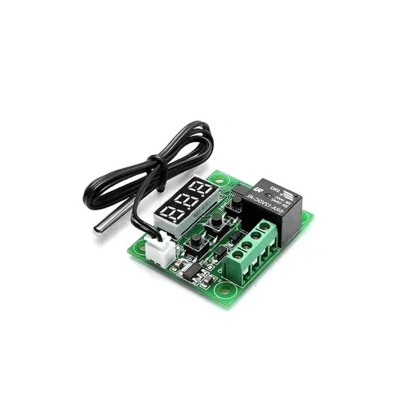
W1209 Digital Temperature Controller Thermostat Module with Display and Waterproof Temperature Sensor
[Temperature Sensor] XH W1209 12V Digital Temperature Control Module + Display and NTC Temp Sensor This is XH W1209 digital temperature controller Module W/ Display and NTC Waterproof Temperature Sensor. W1209 Mini thermostat Temperature controller is low-cost 12V Temperature controller with 7-segment display and 3 switch keypad for setting temperature and other parameters. The module features an NTC thermistor temperature sensing and has an accuracy of 0.1 C. The XH W1209 digital temperature controller Module W/ Display and NTC Waterproof Temperature Sensor is an incredibly low cost yet highly functional thermostat controller. With this module, you can intelligently control power to most types of electrical device based on the temperature sensed by the included high accuracy NTC temperature sensor. Although this module has an embedded microcontroller no programming knowledge is required. 3 tactile switches allow for configuring various parameters including on & off trigger temperatures. The onboard relay can switch up to a maximum of 240V AC at 5A or 14V DC at 10A. We can display current temperature in degrees Centigrade via its 3 digit seven segment display and the current relay state by an onboard LED. DISPLAYING THE CURRENT TEMPERATURE The thermostat will display the current temperature in °C by default. When in any other mode making no input for approximately 5 seconds will cause the thermostat to return to this default display. SETTING THE TRIGGER TEMPERATURE To set the trigger temperature press the button marked ‘SET’. The seven-segment display will flash. You can now set a trigger temperature (in °C) using the ‘+’ and ‘-‘ buttons in 0.1° increments. If we didn’t press any buttons for approximately 2 seconds the trigger temperature will be store and the display will return back to the current temperature. SETTING THE PARAMETERS To set any parameter first long press the ‘SET’ button for at least 5 seconds. The seven-segment display should now display ‘P0’. This represents parameter P0. Pressing the ‘+’ or ‘-‘ buttons will cycle through the various parameters (P0 to P6). Pressing the ‘SET’ button whilst any of these parameters are displayed will allow you to change the value for that parameter using the ‘+’ and ‘-‘ buttons. When finished setting a parameter press the set button to exit that option. If no buttons are pressed for approximately 5 seconds the thermostat will exit the parameter options and will return back to the default temperature display. SETTING THE COOLING OR HEATING PARAMETER P0 The parameter P0 has two settings, C and H. When setting to C (default) the relay will energize when the temperature is reached. Use this setting if connecting to an air-conditioning system. When set to H the relay will de-energize when the temperature is reached. Use this setting if controlling a heating device. SETTING THE HYSTERESIS PARAMETER P1 This sets how much change in temperature must occur before the relay will change state. For example, if set to the default 2oC and the trigger temperature has been set to 25oC, it will not de-energize until the temperature falls back below 23oC. Setting this hysteresis helps stop the thermostat from continually triggering when the temperature drifts around the trip temperature. SETTING THE UPPER LIMIT OF THE THERMOSTAT PARAMETER P2 This parameter limits the maximum trigger temperature that can be set. It is useful as a safety to stop an excessively high trigger temperature from accidentally being set by the user. SETTING THE LOWER LIMIT OF THE THERMOSTAT PARAMETER P3 This parameter limits the minimum trigger temperature that can be set. It is useful as a safety to stop an excessively low trigger temperature from accidentally being set by the user. SETTING TEMPERATURE OFFSET CORRECTION PARAMETER P4 Should you find there is a difference between the displayed temperature and the actual temperature; (for instance, if the temperature probe is on a long run of cable) you can make minor corrections to the temperature reading with this parameter. SETTING THE TRIGGER DELAY PARAMETER P5 To reach trigger temperature this parameter allows for delaying switching of the relay. The parameter can be set in one-minute increments up to a maximum of 10 minutes. SETTING THE HIGH-TEMPERATURE ALARM PARAMETER P6 Setting a value for this parameter will cause the relay to switch off when the temperature reaches this setting. The seven-segment display will also show ‘—‘ to indicate an alarm condition. The relay will not re-energize until the temperature falls below this value. The default setting is OFF.
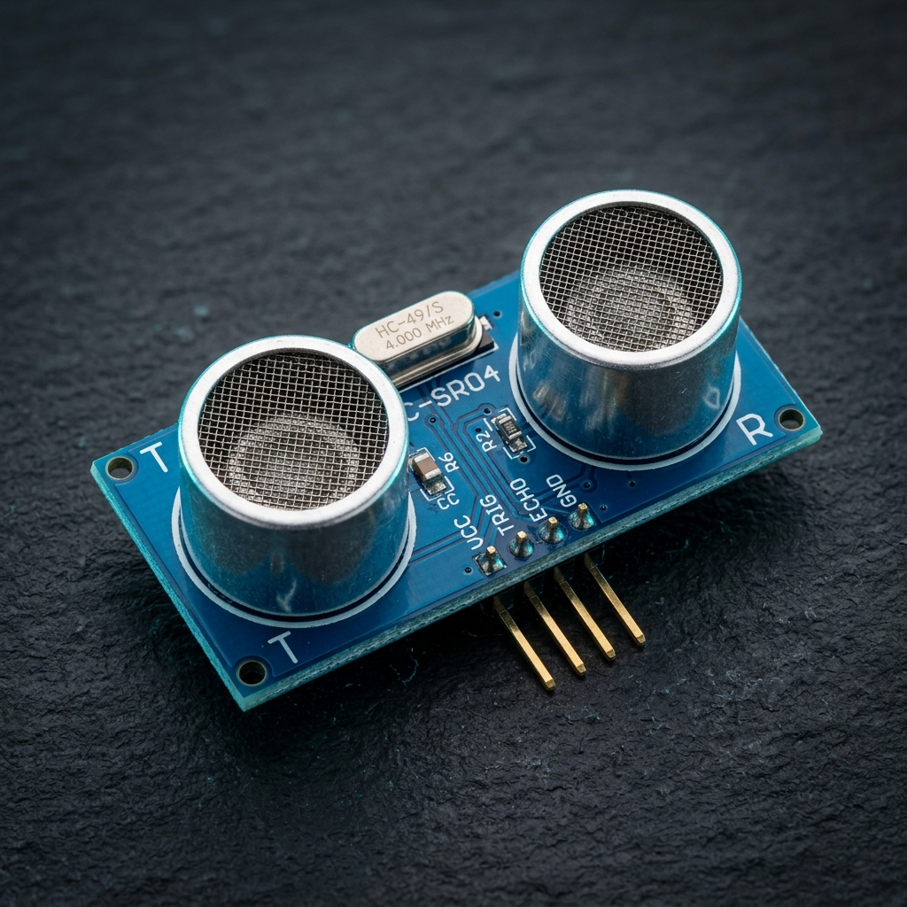
HC-SR04-Ultrasonic Range Finder
[Ultrasonic Sensor] This HC-SR04-Ultrasonic Range Finder is a very popular sensor that is found in many applications where it requires measuring distance and detecting objects. The module has two eyes like projects in the front which forms the Ultrasonic transmitter and Receiver. The HC-SR04 ultrasonic sensor uses sonar to determine the distance to an object like bats or dolphins do. This Ultrasonic Sensor module is a transmitter, a receiver, and a control circuit in one single pack!! It has very handy and compact construction. It offers excellent range accuracy and stable readings in an easy-to-use package. Its operation is not affected by sunlight or black material like Sharp rangefinders are (although acoustically soft materials like cloth can be difficult to detect). The Trigger and the Echo pins are the I/O pins of this module and hence they can be connected to the I/O pins of the microcontroller/Arduino. When the receiver detects the return wave the Echo pin goes high for a particular amount of time which will be equal to the time taken for the wave to return back to the sensor. Ultrasonic Ranging Module HC-SR04 provides 2cm-400cm non-contact distance sensing capabilities, Ranging accuracy up to 3mm. Wiring +5V(positive) Trig(control) Echo(receive) GND(negative) Features : Measures the distance within a wide range of 2cm to 400cm Stable performance Accurate distance measurement High-density Small blind distance Package Includes: 1 x HC-SR04-Ultrasonic Range Finder