
All products · 19 of 1440
Electronics, sensors, robotics kits, PC components, peripherals — everything Unik Systems carries, in one place.
 Only 1 left
IOT Health Kit
MCU: ESP32 (good ADC/BLE). Sensors: pulse sensor/PPG module, body temp sensor, SpO2 module optional. Data logging: serial/cloud. Power: 5V USB. Educational use, non-clinical.
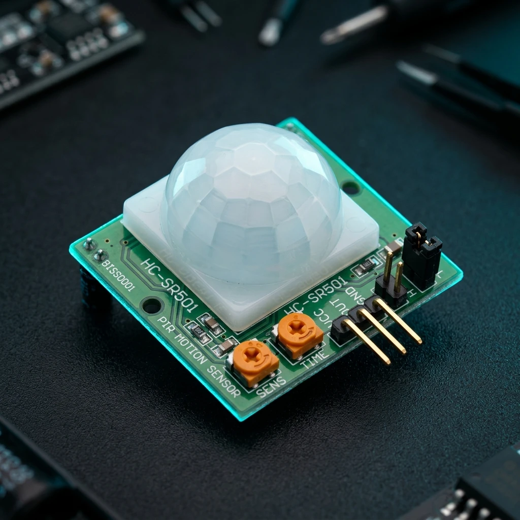
PIR Motion Detector Module
Outputs high digital pulse when motion is detected.
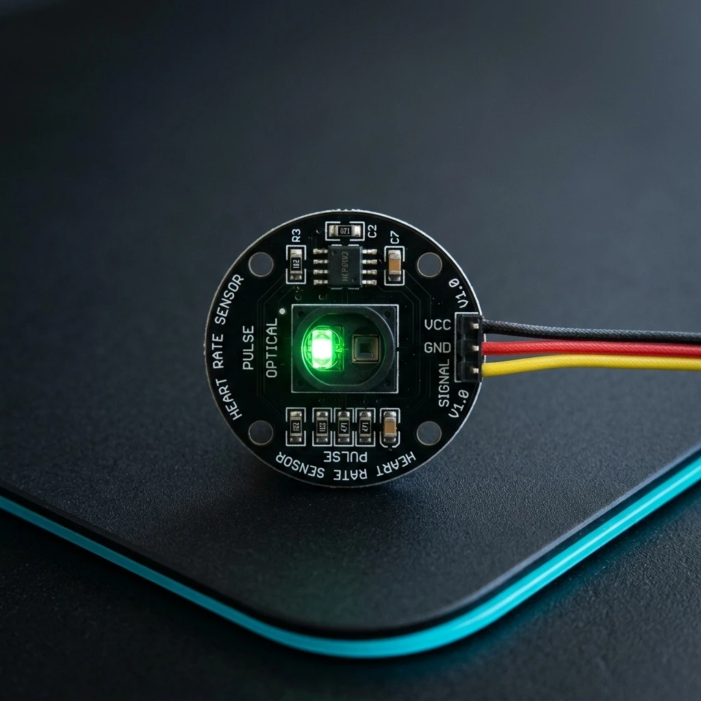
Pulse Rate Heart Sensor
Pulse rate sensor (finger-based, worn on finger or earlobe). 3-5V working voltage.
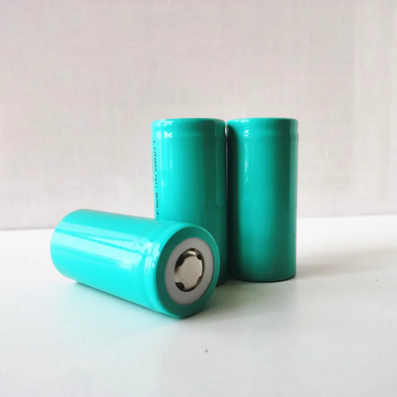
Blivex LFP32700 3.2V 6Ah LiFePO₄ Rechargeable Battery Cell
[LiFePO4 Battery Cell] 🔋 Blivex LFP32700 3.2V 6Ah LiFePO₄ Rechargeable Battery Cell High Capacity • Long Cycle Life • High Discharge Performance • Ideal for Energy Storage & Electric Vehicles The Blivex LFP32700 3.2V 6Ah LiFePO₄ Rechargeable Cell is a premium cylindrical lithium iron phosphate (LiFePO₄) battery designed for high-performance energy storage and power applications. Featuring a nominal voltage of 3.2V, 6Ah capacity, and up to 18A continuous discharge current, this cell delivers stable output voltage, excellent safety, and long service life. The specification identifies the product as a LFP32700-6.0Ah LiFePO₄ cylindrical rechargeable cell. Manufactured with a robust steel enclosure, the battery offers excellent resistance to vibration, shock, and harsh operating conditions while maintaining low self-discharge and high energy efficiency. It is suitable for battery packs used in electric vehicles, solar energy storage systems, portable power stations, communication backup systems, robotics, and industrial equipment. The datasheet also highlights its sturdy steel case, high capacity, long cycle life, stable output voltage, and good high/low temperature performance. Datasheet : Click Here To Open ⭐ Features High-capacity 6Ah LiFePO₄ cylindrical cell Nominal voltage of 3.2V Excellent cycle life of 2000+ cycles High continuous discharge capability up to 18A (3C) Peak pulse discharge current up to 30A (5C) Low internal resistance (≤8mΩ) Stable output voltage Low self-discharge High safety and thermal stability Sturdy pressure-resistant steel casing Excellent vibration and shock resistance Suitable for battery pack assembly 📋 Technical Specifications Brand: Blivex Model: LFP32700-6.0Ah Battery Chemistry: Lithium Iron Phosphate (LiFePO₄) Battery Type: Cylindrical Rechargeable Cell Nominal Voltage: 3.2V Nominal Capacity: 6.0Ah Energy Density: 142Wh/kg Internal Resistance: ≤8mΩ (AC, 1000Hz) Limited Charge Voltage: 3.65V Charge Method: CC/CV Standard Charge Current: 0.5C Maximum Charge Current: 1C Charge Cut-off Current: 0.3A Discharge Cut-off Voltage: 2.0V Standard Discharge Current: 6A (1C) Maximum Continuous Discharge Current: 18A (3C) Maximum Pulse Discharge Current: 30A (10 seconds) Cycle Life: 1500 Cycles (25°C, 100% DOD) Charge Temperature: 0°C to 60°C Recommended Charge Temperature: 15°C to 40°C Discharge Temperature: -30°C to 60°C Recommended Discharge Temperature: 15°C to 40°C Cell Diameter: 32.2 ± 0.3mm Cell Height: 70.5 ± 0.3mm Weight: 135 ± 5g These specifications are taken from the manufacturer's datasheet. 🔧 Applications Suitable for: Solar Energy Storage Systems Portable Power Stations Home Energy Storage UPS Backup Systems Electric Scooters Electric Tricycles Electric Four-Wheel Vehicles Electric Logistics Vehicles Battery Pack Manufacturing Communication Backup Power Industrial Energy Storage Robotics Projects DIY LiFePO₄ Battery Packs Marine & RV Power Systems The manufacturer lists applications including electric two-wheel vehicles, tricycles, logistics vehicles, special vehicles, portable energy storage, household energy storage, industrial energy storage, and communication backup power. 📦 Package Includes 1 × Blivex LFP32700 3.2V 6Ah LiFePO₄ Rechargeable Battery Cell ⚠️ Note Use only with a compatible LiFePO₄ charger and an appropriate Battery Management System (BMS). Do not short-circuit, crush, puncture, disassemble, or expose the battery to fire or excessive heat. Store the battery in a cool, dry place when not in use. Product appearance may vary slightly depending on the manufacturing batch. The datasheet includes additional handling, storage, and safety precautions for transportation, storage, and battery use.
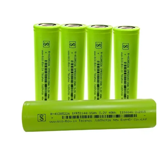
A Grade 3.2V 15Ah 3C 48Wh 3000 Cycles Prismatic Lithium Ion Lipo4 33140 Battery
[LiFePO4 Battery Cell] 32140 15Ah Battery Specification Overview The 15Ah 32140 is a lithium iron phosphate (LiFePO4/LFP) battery in the 32140 cylindrical format (32mm diameter x 140mm height). It's designed for high-capacity, high-cycle-life applications, particularly in energy storage and electric vehicles. Here's a detailed breakdown: Key Specifications • Model: JSK-32140 (or similar variant) • Chemistry: LiFePO4 (LFP) • Nominal Capacity: 15Ah (15000mAh) • Nominal Voltage: 3.2V • Charge Voltage: 3.65V (max) • Discharge Cut-off: 2.5V • Max Continuous Discharge: 30A (2C) • Peak Discharge (pulse): 60A (4C, ≤3 sec) • Standard Charge Current: 7.5A (0.5C) • Fast Charge Possible: Up to 15A (1C) • Cycle Life: 2000+ cycles (to 80% capacity) • Dimensions: 32mm × 140mm • Weight: ~450g (varies by manufacturer) • Operating Temp: ◦ Charge: 0°C to 45°C ◦ Discharge: -20°C to 60°C Key Features ✅ High Capacity – 15Ah is substantial for a single cell, ideal for energy storage. ✅ Long Cycle Life – 2000+ cycles (far exceeding standard Li-ion/NMC batteries). ✅ Safety – LiFePO4 chemistry is non-flammable and stable under abuse. ✅ High Discharge Capability – 30A continuous (suitable for power tools, small EVs). Common Applications • Solar energy storage systems (home/grid storage) • Electric bikes/scooters (as part of a battery pack) • Power tools (replacing lead-acid or NMC packs) • Marine/RV power systems • Backup power stations Safety & Handling No protection circuit needed (LiFePO4 is inherently safer than NMC/Li-ion). Use a LiFePO4-compatible charger (3.65V max, not 4.2V Li-ion chargers). Avoid short-circuiting – Can still deliver dangerous current. Storage: Store at ~50% charge in a cool, dry place. WARNING: Do NOT expose the battery to water Do NOT expose the battery to fire & high temperature Do NOT short circuit, crush or disassemble Only use LiFePO4 charger Storage at 50% capacity, recharge every 3 months. The storage area should be clean, cool, dry and ventilated. Grade A 100% brand new
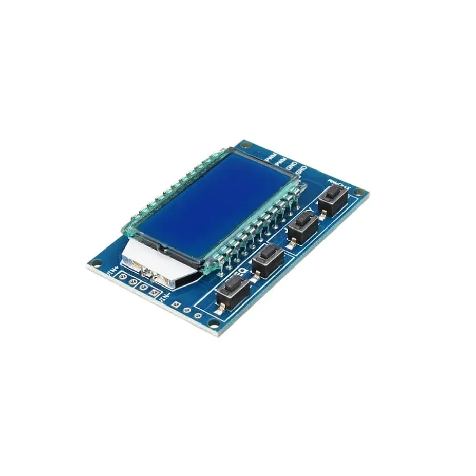
XY-LPWM Signal Generator PWM Pulse Frequency Duty Cycle Adjustable Module LCD Display Module
XY-LPWM Signal Generator PWM Pulse Frequency Duty Cycle Adjustable Module LCD Display Module is a two-channel PWM signal generator. It has dedicated switches for adjusting the frequency and duty cycle separately. Using this module PWM output, frequency and duty cycle can be set as per requirements. Communication Standard: 9600 bps Data bits: 8 Stop bit: 1 Check digit: none Flow control: none Set the frequency of the PWM “F101”: Set the frequency to 101 Hz (001 to 999) “F1.05”: set the frequency of 1.05 kHz (1.00 ~ 9.99) “F10.5”: Set the frequency to 10.5kHz (10.0 ~ 99.9) “F1.0.5”: set the frequency of 105kHz (1.0.0 ~ 1.5.0) Set the PWM duty cycle “DXXX”: set the PWM duty cycle to XXX; (001 ~ 100) Such as D050, set the PWM duty cycle is 50% Read the set parameters Send a “read” string to read the set parameters. Set successfully return: DOWN; Setup failed to return: FALL. Application: This is used to drive a stepper motor driver’s square wave. Generate an adjustable pulse for MCU. Generate an adjustable pulse for controlling relative circuit (PWM adjust lightspeed, etc). Used as a square wave signal generator for experimental development and use. Parameter Settings: The module has 4 switches, two for frequency adjustment and two for duty cycle adjustment. This module can generate frequencies between 1Hz and 150kHz, with automatic switching for different ranges. Frequency is divided into four ranges, automatic switching: 1. XXX (no decimal point): the smallest unit is 1Hz, the value range of 1Hz ~ 999Hz; 2. X.XX (decimal point in the hundred) the smallest unit is 0.01Khz, the range of 1.00Khz ~ 9.99Khz; 3. XX.X (decimal point in ten): the smallest unit is 0.1Khz; value range of 10.0KHz ~ 99.9KHz 4. X.X.X (decimal point in ten and hundred): the smallest unit is 1Khz; value range 1KHz ~ 150KHz 5. e.g. frequency display: 100 indicates PWM output 100Hz pulse; 1.01 indicates PWM output 1.01K pulse; 54.1 indicates that the PWM output has a pulse of 54.1 kHz; 1.2.4 indicates that the PWM output is 124 kHz pulse; Duty cycle range: 1 – 100%. In case of a power outage or if the module is powered down, the parameters that are set are saved automatically, so there is no need to set the parameters again. Single touch for increasing or decreasing single unit and long press for fast increasing or decreasing. Features: LCD display for frequency and duty cycle. Wide frequency range. High precision. Serial communication(TTL based). Package Includes: 1 x XY-LPWM Signal Generator PWM Pulse Frequency Duty Cycle Adjustable Module LCD Display Module.
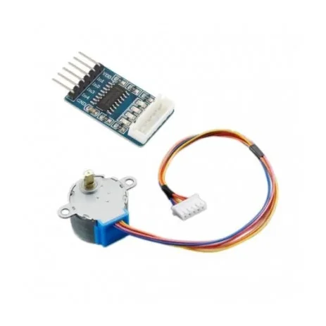
Stepper Motor(28YBJ-48) with SMD ULN2003 Driver Board
[Servo Motor] The 28BYJ-48 Stepper Motor with ULN2003 Driver Board is a compact, reliable, and low-cost 5V geared stepper motor kit designed for Arduino, robotics, automation, and embedded control applications. This motor features a 4-phase, 5-wire configuration with an integrated reduction gearbox, delivering high torque and precise positioning at low speeds. One of the biggest advantages of a stepper motor is its ability to operate accurately in an open-loop control system, eliminating the need for expensive feedback sensors or encoders. The motor position is precisely controlled by simply counting the input step pulses. The included ULN2003 driver board acts as a signal amplifier, allowing low-power control signals from microcontrollers such as Arduino, Raspberry Pi, ESP32, and 8051 to safely drive the stepper motor. The driver board also features four LED indicators (A, B, C, D) that display the working status of each phase in real time, making testing and debugging easy. With its compact size, plug-and-play connector, stable operation, and high reliability, this stepper motor kit is ideal for robot arms, CNC projects, camera sliders, 3D mechanisms, automation systems, and educational electronics projects. ⭐ KEY FEATURES ✔ 28BYJ-48 Mini Geared Stepper Motor – 5V DC✔ 4-Phase, 5-Wire Configuration✔ Includes ULN2003 Stepper Motor Driver Board✔ Open-Loop Precise Control – No encoder required✔ Built-in Gear Reduction for Higher Torque✔ Plug-and-Play Interface – Easy connection✔ Phase LED Indicators on driver board✔ Compact size, lightweight & reliable✔ Perfect for Arduino, robotics & automation projects 🔧 TECHNICAL SPECIFICATIONS Stepper Motor Model: 28BYJ-48 Supply Voltage: 5V DC (commonly used version) Number of Phases: 4 Wires: 5 Stride Angle: 5.625° × 1/64 (with gearbox) Gear Reduction Ratio: 1:64 (approx.) Dimensions: 44 × 44 × 28 mm (L × B × H) Type: Geared Stepper Motor Driver Board Driver Model: ULN2003 Input Interface: Standard 5-pin connector Indicators: 4 Phase LED status indicators Function: Signal amplification & motor driving 🎯 APPLICATIONS Arduino & microcontroller projects Robotics & automation systems Camera sliders & pan-tilt systems CNC & 3D motion mechanisms Educational electronics kits Smart home & IoT projects 📦 PACKAGE INCLUDES 1 × 28BYJ-48 5V Stepper Motor 1 × ULN2003 Stepper Motor Driver Board
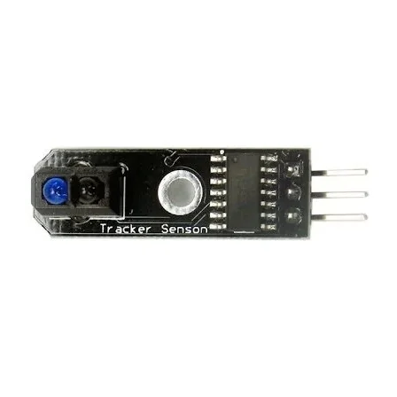
Line Tracker Sensor Module HW-006 V1.3
[IR and PIR Sensors] Description The HW-006 V1.3 TCRT5000 IR reflex or line tracker sensor module is based on an infrared reflectance sensor. This is typically mounted at the end of a line that follows the robot chassis. This small tracking sensor module can detect not only transitions from light to dark lines but also objects in front of it. It is ideally used for detecting white or black lines., obstacle detection and meter pulse data sampling. Wiring: VCC: Connect the positive wire of the power supply (5V) GND: Connected to the negative wire of the power supply OUT: High/Low level- Output switching signal SPECIFICATIONS Model/Name HW-006 V1.3 Type Tracker Sensor No of Pin 03 Dimension 35*10*8mm Working Voltage 5V DC Peak Operating Current 20mA to 33mA Output  Digital (0,1) Country of Origin China
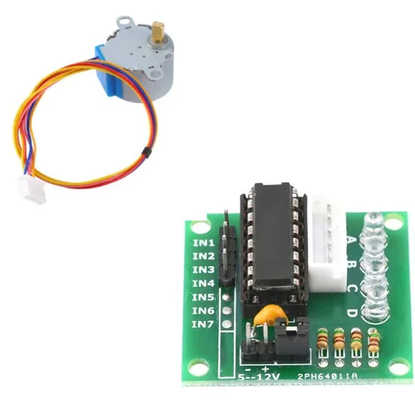
Stepper Motor(28YBJ-48) with ULN2003 Driver Board
[Servo Motor] The 28BYJ-48 Stepper Motor with ULN2003 Driver Board is a compact, reliable, and low-cost 5V geared stepper motor kit designed for Arduino, robotics, automation, and embedded control applications. This motor features a 4-phase, 5-wire configuration with an integrated reduction gearbox, delivering high torque and precise positioning at low speeds. One of the biggest advantages of a stepper motor is its ability to operate accurately in an open-loop control system, eliminating the need for expensive feedback sensors or encoders. The motor position is precisely controlled by simply counting the input step pulses. The included ULN2003 driver board acts as a signal amplifier, allowing low-power control signals from microcontrollers such as Arduino, Raspberry Pi, ESP32, and 8051 to safely drive the stepper motor. The driver board also features four LED indicators (A, B, C, D) that display the working status of each phase in real time, making testing and debugging easy. With its compact size, plug-and-play connector, stable operation, and high reliability, this stepper motor kit is ideal for robot arms, CNC projects, camera sliders, 3D mechanisms, automation systems, and educational electronics projects. ⭐ KEY FEATURES ✔ 28BYJ-48 Mini Geared Stepper Motor – 5V DC✔ 4-Phase, 5-Wire Configuration✔ Includes ULN2003 Stepper Motor Driver Board✔ Open-Loop Precise Control – No encoder required✔ Built-in Gear Reduction for Higher Torque✔ Plug-and-Play Interface – Easy connection✔ Phase LED Indicators on driver board✔ Compact size, lightweight & reliable✔ Perfect for Arduino, robotics & automation projects 🔧 TECHNICAL SPECIFICATIONS Stepper Motor Model: 28BYJ-48 Supply Voltage: 5V DC (commonly used version) Number of Phases: 4 Wires: 5 Stride Angle: 5.625° × 1/64 (with gearbox) Gear Reduction Ratio: 1:64 (approx.) Dimensions: 44 × 44 × 28 mm (L × B × H) Type: Geared Stepper Motor Driver Board Driver Model: ULN2003 Input Interface: Standard 5-pin connector Indicators: 4 Phase LED status indicators Function: Signal amplification & motor driving 🎯 APPLICATIONS Arduino & microcontroller projects Robotics & automation systems Camera sliders & pan-tilt systems CNC & 3D motion mechanisms Educational electronics kits Smart home & IoT projects 📦 PACKAGE INCLUDES 1 × 28BYJ-48 5V Stepper Motor 1 × ULN2003 Stepper Motor Driver Board
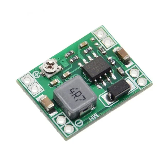
Mini MP1584 DC-DC 3A Adjustable Buck Module
[Step Down Buck Converter] The Mini MP1584 DC-DC 3A Adjustable Buck module is ultra small adjustable 0.8V to 20V output DC to DC step-down Buck converter that uses an MP1584EN high frequency switching regulator and integrated high voltage power MOSFET. It features a soft start, thermal shutdown, and under-voltage lockout (UVLO) to protect the module from operating at insufficient supply voltage. Small size, lightweight, low internal power consumption, and wide input voltage range of 4.5V to 28V make this module suitable for a variety of different applications where small size and lightweight voltage conversion is needed, including RC cars and airplanes, quadcopters, robotics, Arduino modules, and DIY devices. Applications: DIY 8051 / AVR / ARM / PIC / Arduino / Raspberry-Pi projects Robotics Breadboard power supply Manual speed adjustment of small DC motors Power Supply for RC project planes, cars, helicopters Universal Battery Elimination Circuit (UBEC) for 2S-6S lipo battery pack Receiver/servo power supply Communications equipment power supply Mobile equipment power supplies Note: PCB board color may be different from the actual product. Features: Wide 4.5V to 28V Operating Input Range High-Efficiency Pulse Skipping Mode for Light Load Ceramic Capacitor Stable Internal Soft-Start Internally Set Current Limit without a Current Sensing Resistor
 Out of stock
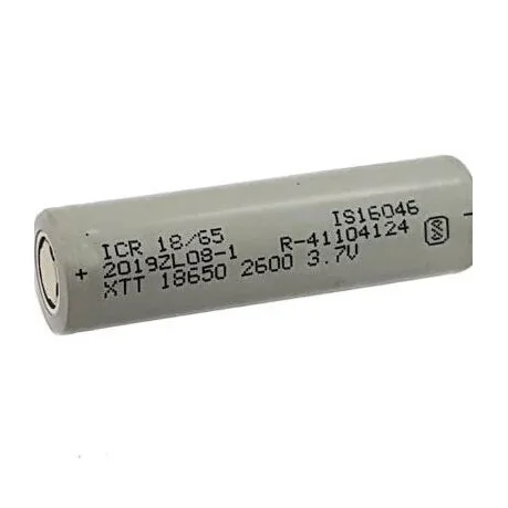
XTT 2600 mAh Lithium Ion cell(NMC) Good Quality
[Lithium Battery Cell] 2600 Mah Rechargeable Battery 18650 Li-Ion 3.7V (Grade – A) Li-Ion Rechargeable Battery 2600 mAh BIS Certified Battery lithium-ion cell Brand –XTT Voltage – 3.7v Mah – 2600mah Discharge rate – 1c Flat Head Top Side Application – Solar & Other Continous Power Battery Pack Warranty:- One Month Replacement Warranty (Condition Apply) Battery Type 18650 Battery Flat Head Capacity 2600mAh Voltage 3.7V Max Charge Voltage 4.2V Discharge Cut-off Voltage 25V Standard Charge Current 0.5C Max Charge Current 1C Standard Discharge Current 1C Max. Continuous Discharge Current 5C Pulse Discharge Discharge at 10’s / Internal Resistance ≤30mΩ Cycle Life 600Times Dimension 18.4*65.2mm Weight 45g Operating Temperature Charging: 0 to 45 °C, Discharging: -20 to 60°C
 Out of stock
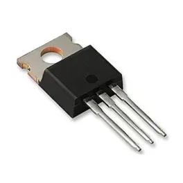
IRF740 MOSFET – 400V 10A N-Channel Power MOSFET TO-220
[Mosfet] IRF740 MOSFET – N-Channel Transistor IRF740 is type of N-Channel enhancement mode power field effect transistors which are using planar, DMOS technology. This advanced technology has been especially tailored to minimize on-state resistance, provide superior switching performance, and withstand high energy pulse in the avalanche and commutation mode. These devices are well suited for high efficiency switch mode power supplies and electronic lamp ballasts based on half bridge.. Specifications Drain-Source Volt (Vds): 400V Drain-Gate Volt (Vdg): 400V Gate-Source Volt (Vgs): 20V Drain Current (Id): 10A Power Dissipation (Ptot): 125W Type: N-Channel Features Low gate charge Low Crss (typical 35 pF) Fast switching 100% avalanche tested Improved dv/dt capability Lead-Free, RoHS Compliant
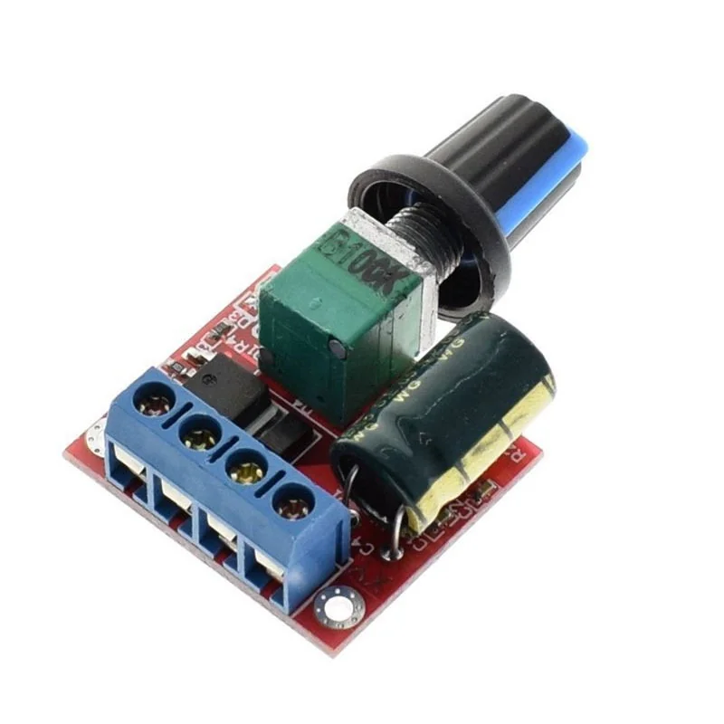
3V 6V 12V 24V 35V PWM DC Motor Speed Regulator
[Brushed DC motor Driver] 3V 6V 12V 24V 35V PWM DC Motor Speed Regulator is a Mini Style DC Motor Speed Regulator controls the speed of a DC motor by adjusting Pulse-Width-Modulated (PWM). Precautions: DC motor governor input is DC, can not directly connect to the AC (for example home 220V AC), otherwise, it will burn! DC power supply positive and negative terminals do not reverse, otherwise, the governor may be damaged. The motor can be positive or negative when the direction of operation and expectations do not match, you can adjust the line order to change the direction. Adjust the potentiometer knob to change the governor output duty cycle, the motor speed changes. Features: Mini DC 4.5-35V 5A PWM Motor Speed Controller. Wide voltage DC motor speed controller. Operating voltage: DC4.5V-35V Output current: 0-5A Output power: 90W (max) PWM duty cycle: 1% -100%. Package Includes: 1 x 3V 6V 12V 24V 35V PWM DC Motor Speed Regulator
 Out of stock
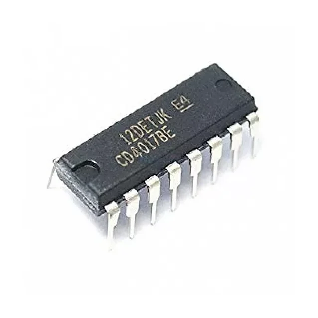
4017 Decade Counter IC
[Timer,Clock,Counter ICs] DESCRIPTION:- This IC 4017 is a 16-pin counter IC. It is a CMOS decade counter cum decoder circuit. It can count from zero to ten and its outputs are decoded. This saves a lot of board space and time required to build our circuits when our application demands using a counter followed by a decoder IC. IC 4017 is a digital counter plus decoder circuit. CD4017 Pin Configuration :- Pin Number Pin Name Description 1 to 7 and 9,10,11 Output pins Q0 to Q9 These are the 10 output pins on which the counting occurs, they are not in order hence verify pin diagram above 8 Vss or Ground Connected to the Ground of the circuit 12 Carry Out (CO) This pin goes high after the IC counts from 1 to 10. This is used as carry while counting. 13 Clock Enable (EN) This is an input which when made high will hold the count at the current state 14 Clock The counting happens when this clock pulse goes high , this pin is normally connected to 555 timer or other uC to produce a pulse 15 Resets As the name suggests this pin resets the count back to 1 16 Vdd / Vcc Connects to the supply voltage typically +5V Features:- High speed 16 pin CMOS Decade counter Supports 10 decoded outputs Wide supply voltage range from 3V to 15V, typically +5V TTL compatible Maximum Clock Frequency: 5.5Mhz Available in 16-pin PDIP, GDIP, PDSO packages Where to use CD4017 IC:- The IC CD4017 is used for counting applications, it has the capability to turn on 10 outputs sequentially in a pre-defined time and reset the count or hold it when required. It also has the capability to indicate the status of counting using Carry pin. This is commonly used for Led chasers and other logical output projects, so if you are looking for a sequential decoded counting IC that can count up to 10 then this IC will be your right choice How to use a CD4017 IC:- The IC can work from 3V to 15V, but normally powered with +5V to the Vdd/Vcc pin and the Ground/Vss pin is connected to ground. We have 10 output pins ranging from Q0 to Q9, these pins can be connected to any load but we are using LEDs here as shown in the circuit below. Package Includes :- 1 X 4017 Decade Counter IC
 Out of stock
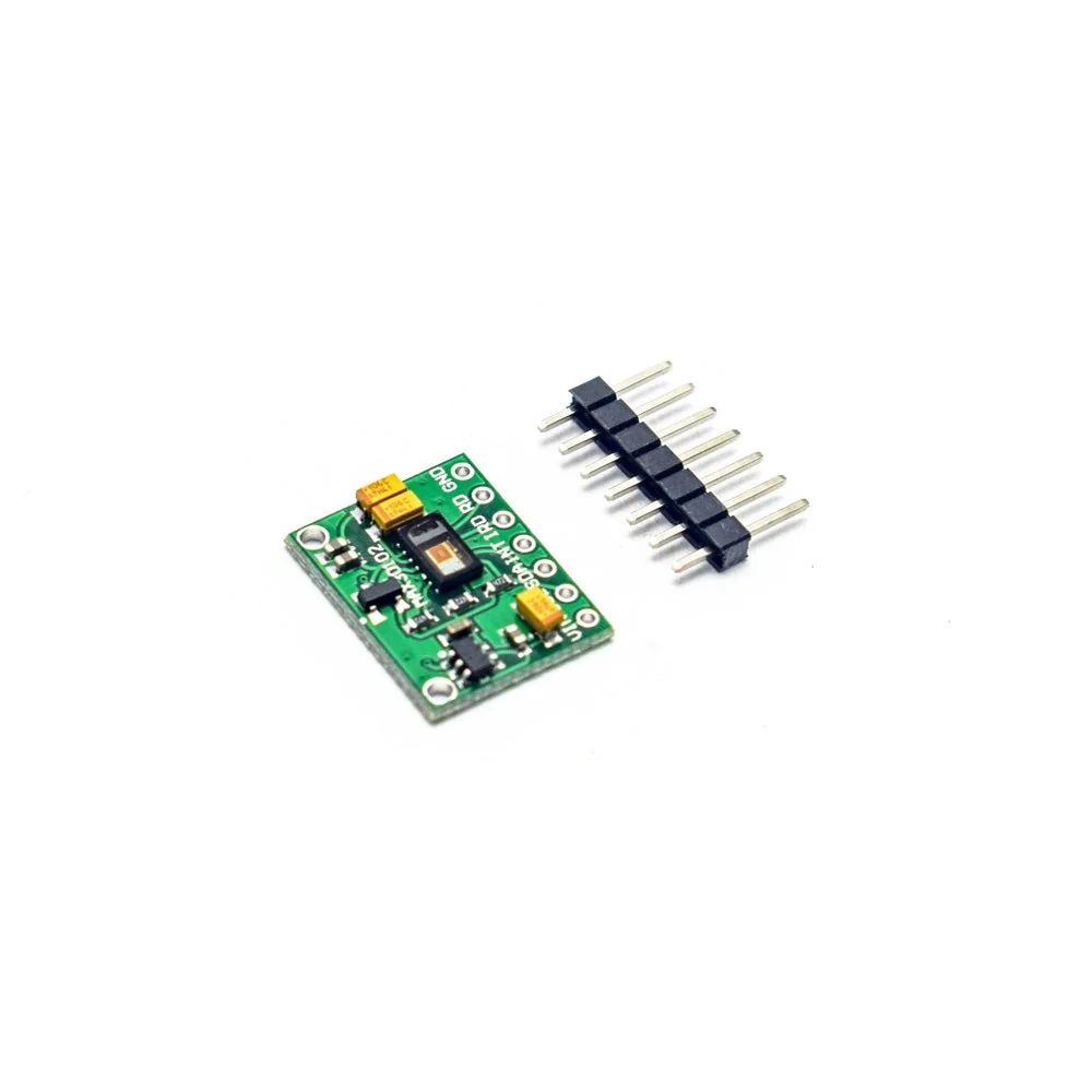
MAX30102 Pulse Oximeter Heart Rate Sensor Module
[Proximity Sensor] MAX30102 is a sensor that combines a pulse oximeter and a heart rate monitor. It’s an optical sensor that measures the absorbance of pulsating blood through a photodetector after emitting two wavelengths of light from two LEDs – a red and an infrared one. This particular LED colour combination is designed to allow data to be read with the tip of one’s finger. It is fully configurable through software registers and the digital output data is stored in a 16-deep FIFO within the device. It has an I2C digital interface to communicate with a host microcontroller. The pulse oximetry subsystem in MAX30102 consists of ambient light cancellation (ALC), 16-bit sigma-delta ADC, and a proprietary discrete-time filter. It has an ultra-low-power operation which makes it ideal for battery-operated systems. MAX30100 operates on a supply in the range of 1.8 to 3.3V. It can be used in wearable devices, fitness assistant devices, medical monitoring devices, etc. This sensor works on 3.3V Devices directly. You can connect it to 3.3V devices like ESP8266, ESP32, etc. directly. To use it with the Arduino UNO, Mega, Nano, etc. use a level shifter in between. Else I2C connection will not work. Features Heart-Rate Monitor and Pulse Oximeter Sensor in LED Reflective Solution Tiny 5.6mm x 3.3mm x 1.55mm 14-Pin Optical Module Integrated Cover Glass for Optimal, Robust Performance Ultra-Low Power Operation for Mobile Devices Programmable Sample Rate and LED Current for Power Savings Low-Power Heart-Rate Monitor (< 1mW) Ultra-Low Shutdown Current (0.7µA) Fast Data Output Capability High Sample Rates Robust Motion Artifact Resilience High SNR -40°C to +85°C Operating Temperature Range
 Out of stock
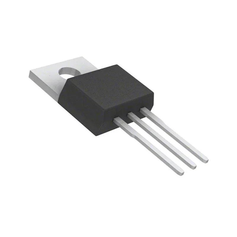
IRFZ44N MOSFET IC DIP
[Mosfet] IRFZ44N Power MOSFETIRFZ44N is an advanced HEXFET Power MOSFETs that utilizes advanced processing techniques to achieve extremely low on-resistance per silicon area. This benefit, combined with the fast switching speed and ruggedized device design that exFAT power MOSFETs are well known for, provides the designer with an extremely efficient and reliable device for use in a wide variety of applications. The TO-220 package is universally preferred for all commercial-industrial applications at power dissipation levels to approximately 50 watts. The low thermal resistance and low package cost of the TO-220 contribute to its wide acceptance throughout the industry. Specification: Application: Electronic Continuous Drain Current: 49A Power Dissipation: 94W Pulsed Drain Current: 160A Features: Advanced Process Technology Ultra-Low On-Resistance Dynamic DV/DT Rating 175 DegreeC Operating Temperature Fast Switching Fully Avalanche Rated Datasheet: Download Package Content: 1 x IRFZ44N Mosfet
 Out of stock
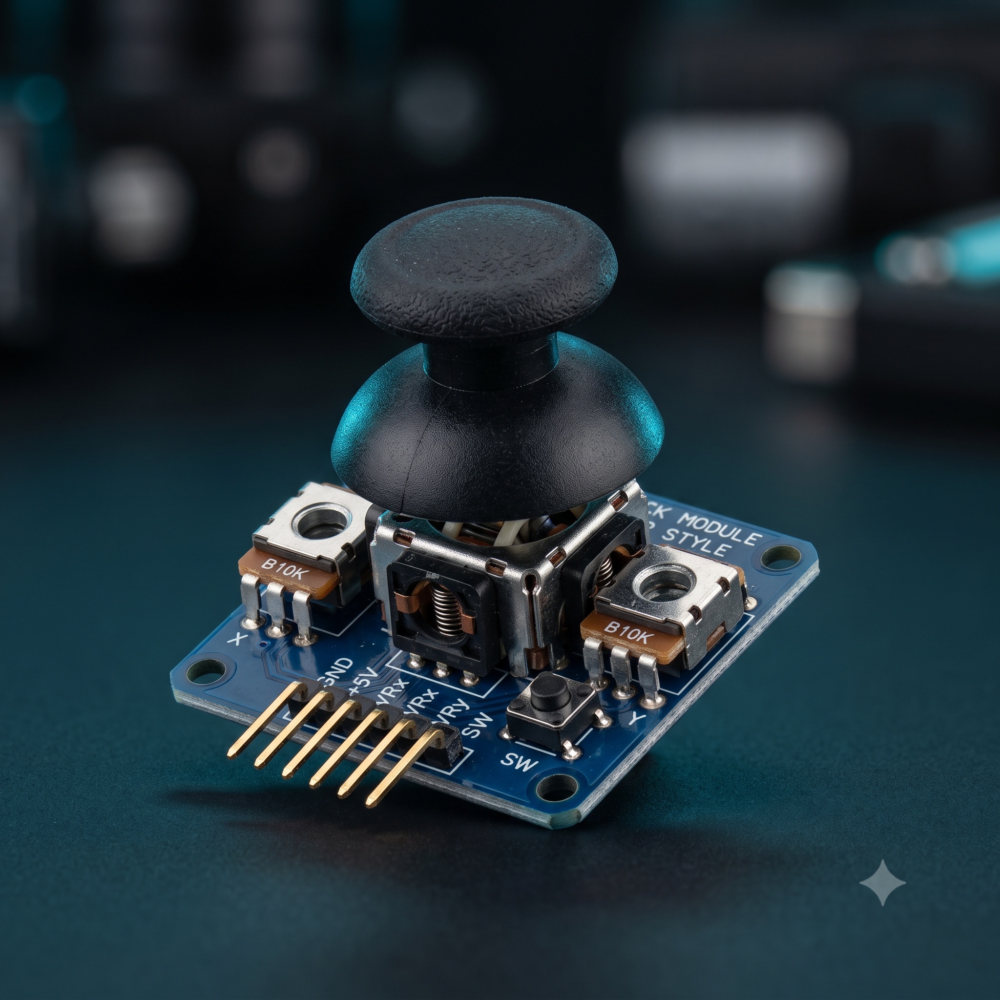
PS2 Joystick Module Breakout Sensor
[Breakout Board] Dual Axis XY Joystick Module This is JoyStick Module PS2 Breakout Sensor very similar to the ‘analog’ joysticks on PS2 (PlayStation 2) controllers. Directional movements are simply two potentiometers – one for each axis. Pots are ~10k each. This joystick also has a select button that is actuated when the joystick is press down. With the help of this Joystick Module, you can measure position coordinates on the X and Y axis by moving the “hat”. It also contains a switch that is press-able by pushing the “hat”.It also contains a switch that is press-able by pushing the “hat” down. Similar to the XBOX controller. The X and Y axes are two 10k potentiometers which control 2D movement by generating analog signals. When the module is in working mode, it will output two analog values, representing two directions. This module uses the 5V power supply, and value, when reading through analog input, would be about 2.5V, a value will increase with joystick movement and will go up till maximum 5V; the value will decrease when the joystick is moved in other direction till 0V. Applications: 1. As square wave signal generator which generates a square wave signal 2. To provide a signal to the stepping motor driver 3. Adjustable pulse generation for chip use 4. Produce variable pulse signal, the control-related circuit (PWM dimming, speed) Module Description: Frequency is divided into three ranges: 1. XXX (no decimal point): the smallest unit is 1Hz, the range 1Hz-999Hz 2. XX.X (decimal point in ten): The minimum unit is 0.1Khz; the range of 0.1KHz-99.9KHz 3. X.X.X.(there is three decimal point): the smallest unit is 1Khz; the range 1KHz-150KHz Frequency Display Example: 1. ”100″ indicates that the PWM output pulse of 100Hz 2. ”54.1″ indicates that the PWM output pulse of 54.1KHz 3. ”1.2.4.” Indicates that the PWM pulse output 124KHz 4. Duty Cycle in the range:0 to 100 5. Three frequencies duty cycle is the same, all the parameters are non-volatile Features: 2.54mm pin interface leads Long service life and stable performance Standard interface and electronic building blocks Widely use in Arduino DIY projects Cross rocker as a two-way 10K resistor, with the rocker in a different direction.
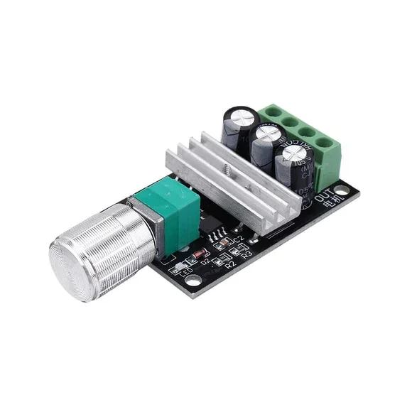
1203B PWM 6V 12V 24V 28V 3Amp DC Motor Speed Regulator
[Brushed DC motor Driver] The 1203B PWM DC Motor Speed Controller Module is a versatile motor control board designed to regulate the speed of brushed DC motors through Pulse Width Modulation (PWM) technology. By varying the duty cycle of the PWM signal, the controller provides smooth and efficient motor speed adjustment without significant power loss. In addition, the module supports a wide operating voltage range from 6V to 28V DC, making it compatible with various DC motors used in robotics, automation systems, DIY electronics, and industrial applications. As a result, users can easily control motor speed according to project requirements. Because of its PWM control method, the module maintains excellent torque even at lower speeds. Furthermore, it offers higher efficiency compared to traditional resistive speed control methods, reducing heat generation and power consumption. The onboard rotary potentiometer allows precise speed adjustment from 0% to 100%, enabling accurate control of motor performance. Moreover, the compact PCB design simplifies installation in space-constrained projects. ⚠️ Note: This module is intended for DC motor speed control only and should not be used as a voltage regulator for LEDs, lighting circuits, or other electronic loads. 🔹 Key Features PWM motor speed control technology Adjustable speed from 0% to 100% Wide operating voltage range High efficiency operation Low heat generation Compact PCB design Easy speed adjustment using potentiometer Stable motor control performance Suitable for brushed DC motors Simple wiring and installation 🔹 Technical Specifications Model: 1203B Product Type: PWM DC Motor Speed Controller Input Voltage: DC 6V – 28V Output Voltage: Linear with Input Voltage Maximum Continuous Current: 3A Peak Current: 5A (Short Duration) Speed Control Range: 0% – 100% Control Method: PWM (Pulse Width Modulation) PWM Frequency: Approx. 13kHz Efficiency: Up to 95% Operating Temperature: -20°C to +60°C Control Type: Rotary Potentiometer Module Dimensions: Approx. 32mm × 50mm × 15mm 🔹 Pin Configuration Motor+ : Motor Positive Terminal Motor- : Motor Negative Terminal Power+ : DC Input Positive (6V–28V) Power- : DC Input Negative (GND) 🔹 Applications This speed controller module is suitable for: DC motor speed control Robotics projects DIY electronics projects Small electric vehicles Cooling fans Water pumps Automation systems Educational projects Hobby motor control applications 🔹 Package Includes 1 × 1203B PWM DC Motor Speed Controller Module
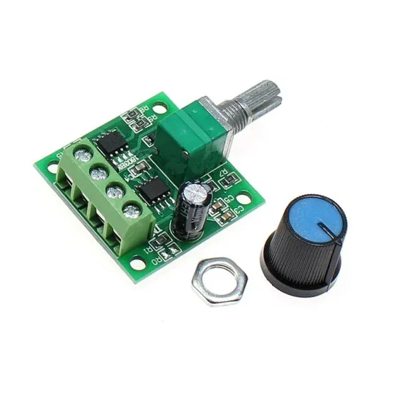
PWM DC Motor Speed Controller 1.8V/3V/5V/6V/12V – 2A
[Brushed DC motor Driver] 1.8V – 12V 2A DC Motor PWM Speed Regulator The DC Motor PWM Speed Regulator 1.8V, 3V, 5V, 6V, 12V-2A speed control switch function for DC Motors allows controlling the direction of a DC motor using a Pulse-Width-Modulated (PWM) DC voltage with a Duty Cycle fully adjustable from 0%-100%. The motor speed controller can easily provide a continuous current of 2A to your DC motor or other DC load. With a resettable fuse, it can automatically break the connection and automatically recover. With a LED indicator and a rotary switch, convenient to use. OPERATING INSTRUCTION: 1. Connect your DC motor (or DC load) to the motor terminals 2. Connect a voltage of 1.8V-12V DC to the circuit making sure of the correct polarity of the connection. Note that the voltage applied to the motor will be the supply voltage applied to the circuit. 3. You can now control the speed of the motor through the potentiometer. Features : Output current : 2A(Max). With a resettable fuse. Equipped with LED indicator. Potentiometer with switch function for PWM adjustment. Package Includes : 1 x PWM DC Motor Speed Controller 1.8V/3V/5V/6V/12V- 2A.