
All products · 22 of 1440
Electronics, sensors, robotics kits, PC components, peripherals — everything Unik Systems carries, in one place.
Arduino Plug & Play
Controller: Arduino UNO/Nano compatible (ATmega328P), 5V logic. Interfaces: Digital I/O, PWM, Analog In, I2C/SPI/UART. USB programming. Plug-and-play sensor ports (JST/RJ/3-pin). Power: USB 5V / DC 7–12V (if UNO).
 Only 2 left
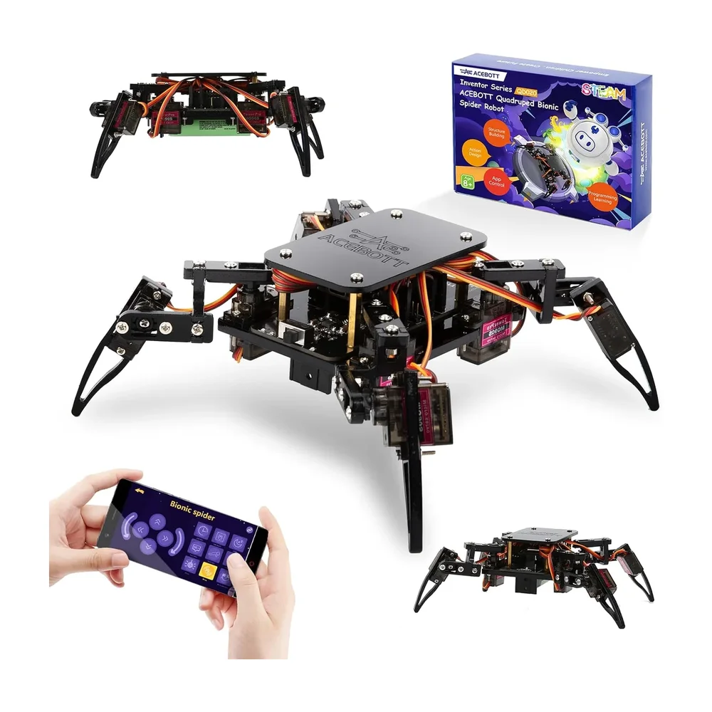
Robotic Spider Kit
Legs: 4/6/8-legged variants. Servos: 8–12 micro servos. Controller: Arduino/ESP32 compatible. Gait programming. Power: 5–6V high-current (2A–5A depending on servos). Frame: acrylic/ABS.
 Only 2 left
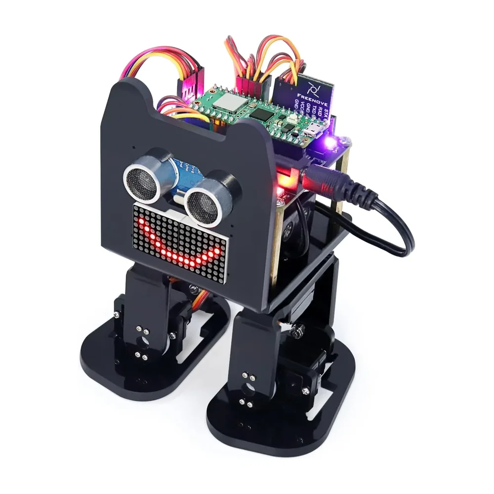
Otto
Biped robot kit. Servos: 4 micro servos (legs/feet). MCU: Arduino Nano compatible. Sensors: ultrasonic + buzzer. Power: 5V (battery pack). Programming: Arduino IDE / block coding. Functions: walk/dance/avoid.
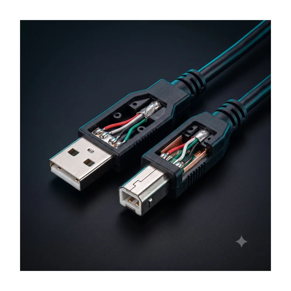
USB Cable (UNO Programming, A to B)
USB Male-A to USB Male-B cable for Arduino UNO.
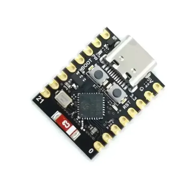
ESP32-C3 Super Mini Development Board With Headers Pins
[ESP Modules] Ultra Compact • Wi-Fi & BLE 5.0 • USB Type-C • Perfect for IoT & Embedded Projects The ESP32-C3 Super Mini Development Board is a compact, feature-rich development board built around the powerful ESP32-C3 SoC from Espressif. Powered by a 32-bit RISC-V single-core processor running at up to 160MHz, it combines 2.4GHz Wi-Fi, Bluetooth 5.0 Low Energy (BLE), and low-power operation in an ultra-small form factor. Designed for IoT, smart home, wireless communication, automation, and embedded system development, the ESP32-C3 Super Mini offers 4MB Flash memory, 400KB SRAM, multiple GPIOs, ADC, PWM, UART, SPI, and I2C interfaces for connecting sensors, displays, relays, and other peripherals. The onboard USB Type-C interface simplifies programming and power supply, while the built-in USB-to-Serial functionality enables quick firmware uploading without requiring additional programmers. Fully compatible with Arduino IDE, ESP-IDF, PlatformIO, and MicroPython, it is suitable for beginners, students, makers, and professional developers. Its ultra-compact breadboard-friendly design makes it ideal for portable and space-constrained projects where performance, wireless connectivity, and energy efficiency are essential. Note: Programming, software configuration, driver installation, firmware flashing, and coding-related issues are not covered under return or replacement. Users are expected to troubleshoot software-related issues independently. ⭐ Features Powerful ESP32-C3 32-bit RISC-V processor CPU frequency up to 160MHz Built-in 2.4GHz Wi-Fi (802.11 b/g/n) Integrated Bluetooth 5.0 Low Energy (BLE) Ultra-compact Super Mini design Breadboard-friendly layout USB Type-C interface for programming and power 4MB onboard Flash memory 400KB SRAM Multiple GPIO, ADC, PWM, UART, SPI & I2C interfaces Low power consumption with Deep Sleep mode Onboard programmable LED Compatible with Arduino IDE, ESP-IDF, PlatformIO & MicroPython Ideal for IoT, automation, robotics, and wireless applications 📋 Technical Specifications Product Type: Development Board Board Model: ESP32-C3 Super Mini Microcontroller: ESP32-C3 Processor Architecture: 32-bit RISC-V CPU Frequency: Up to 160MHz Core: Single Core Flash Memory: 4MB SRAM: 400KB Wi-Fi Standard: IEEE 802.11 b/g/n (2.4GHz) Bluetooth: Bluetooth 5.0 Low Energy (BLE) Operating Voltage: 3.3V Input Voltage: 5V via USB Type-C or 3.3V External USB Interface: USB Type-C GPIO: Multiple Digital GPIO Pins Analog Input: Up to 6 ADC Channels PWM: Supported UART: Supported SPI: Supported I2C: Supported USB-to-Serial: Onboard Onboard LED: User Programmable (GPIO8) Power Consumption: Ultra Low (Deep Sleep ≈ 43µA) Dimensions: Approx. 22.5 × 18 mm Headers: Pre-Soldered 🔧 Applications Suitable for: Internet of Things (IoT) Smart Home Automation Wireless Sensor Networks Home Automation Systems Bluetooth Low Energy Devices Wi-Fi Enabled Controllers Robotics Projects Data Logging Systems Remote Monitoring Industrial Automation Portable Embedded Devices Educational Learning DIY Electronics Projects Wearable Electronics Rapid Prototyping 📦 Package Includes 1 × ESP32-C3 Super Mini Development Board Pin Headers ⚠️ Note Programming, firmware installation, software configuration, and driver-related issues are not covered under warranty, return, or replacement. Please verify board compatibility and install the appropriate development environment before programming. Soldered and non-soldered header pin depend on stock
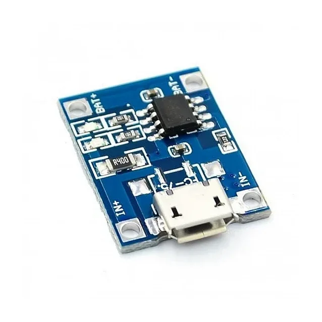
TP4056 1A Li-Ion Lithium Battery Charging Module with Micro USB 3.7V Charger Board
[Li-ion Rechargeable Battery Charger, Lithium Battery Protection Board] The TP4056 1A Li-Ion Lithium Battery Charging Module – Micro USB is a compact and efficient charging board designed for charging single-cell 3.7V lithium-ion and lithium polymer batteries. It features an onboard Micro USB connector, allowing direct charging from USB power sources such as computers, adapters, and power banks. In addition, the module supports external power input through the IN+ and IN- pads, making it suitable for custom battery charging applications and DIY electronics projects. As a result, users can easily integrate the module into portable devices and battery-powered systems. Because of its compact size and lightweight design, the TP4056 module is ideal for space-limited applications. Furthermore, the onboard charging management IC provides stable charging performance with high accuracy and reliable battery protection. The charging current is set to 1A by default, but it can also be adjusted by changing the onboard programming resistor. Moreover, the module includes dual LED indicators for charging status and full-charge indication. This charging module is widely used in power banks, DIY battery chargers, portable electronics, IoT devices, robotics systems, and rechargeable battery projects. 🔹 Key Features TP4056 lithium battery charging IC Onboard Micro USB input interface Suitable for 3.7V Li-Ion and LiPo batteries Default 1A charging current Adjustable charging current support Dual LED charging status indicators Compact and lightweight design High charging accuracy and stable performance Easy integration into DIY projects 🔹 Technical Specifications Product Type: Lithium Battery Charging Module Charging IC: TP4056 Input Interface: Micro USB Input Voltage: 5V DC Battery Type: 3.7V Li-Ion / LiPo Battery Default Charging Current: 1A Adjustable Current Range: 100mA – 1000mA Charging Method: Constant Current / Constant Voltage Charging Indicators: Charging LED & Full Charge LED Mounting Type: PCB Module Body Material: FR4 PCB 🔹 Applications This TP4056 charging module is suitable for many electronic applications, including: DIY power banks Rechargeable battery projects Portable electronics Robotics systems IoT devices Battery charging circuits Arduino projects DIY electronics projects 🔹 Package Includes 1 × TP4056 1A Li-Ion Lithium Battery Charging Module – Micro USB
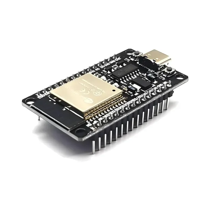
ESP32 Development Board with WiFi & Bluetooth – CH340C USB Type-C
[ESP Modules] The ESP32 Development Board with WiFi & Bluetooth (CH340C, Type-C) is a powerful and versatile microcontroller board designed for modern wireless and IoT applications. It features a dual-core processor and integrated 2.4GHz WiFi and Bluetooth (Classic + BLE) connectivity. This board includes an onboard CH340C USB-to-Serial converter, which allows easy programming and communication without requiring an external crystal oscillator. The USB Type-C port provides a stable and reversible connection for power and data. With a wide range of GPIO pins and peripherals such as ADC, DAC, PWM, UART, SPI, and I2C, this board is perfect for building home automation systems, smart devices, IoT nodes, robotics controllers, sensor networks, web servers, and wireless projects. It is fully compatible with Arduino IDE, ESP-IDF, and MicroPython, making it suitable for beginners, students, and professional developers. 🔹 Key Features Based on ESP32 dual-core microcontroller Built-in WiFi 802.11 b/g/n and Bluetooth v4.2 (Classic + BLE) Onboard CH340C USB-to-Serial converter (no external crystal required) Modern USB Type-C connector for power and programming Dual-core CPU up to 240 MHz for high-performance applications Multiple GPIO pins with ADC, DAC, PWM support Supports Arduino IDE, ESP-IDF, and MicroPython Low-power modes including deep sleep for battery-powered projects Compact design with breadboard-friendly layout Ideal for IoT, automation, robotics, smart home, and DIY electronics 🔹 Technical Specifications Microcontroller: ESP32 CPU: Dual-core Tensilica LX6, up to 240 MHz Flash Memory: 4 MB (typical, may vary by batch) SRAM: 520 KB Wireless Connectivity: WiFi: 2.4 GHz, 802.11 b/g/n Bluetooth: v4.2, Classic + BLE USB Interface: USB Type-C USB-to-Serial Chip: CH340C Operating Voltage: 3.3 V Input Voltage: 5 V via USB Logic Level: 3.3 V GPIO Pins: 30+ multifunction pins Peripherals: ADC, DAC, PWM, UART, SPI, I2C, I2S Clock Frequency: Up to 240 MHz Programming Support: Arduino IDE, ESP-IDF, MicroPython Onboard Components: Reset & Boot buttons, voltage regulator, status LEDs Form Factor: Standard ESP32 Dev Board size 🔹 Applications Internet of Things (IoT) projects Home and industrial automation Smart home devices Robotics and motor control Wireless sensor networks Web servers and cloud-connected devices Educational and training projects DIY electronics and prototyping 🔹 Package Contents 1 × ESP32 Development Board with WiFi & Bluetooth (CH340C, USB Type-C)
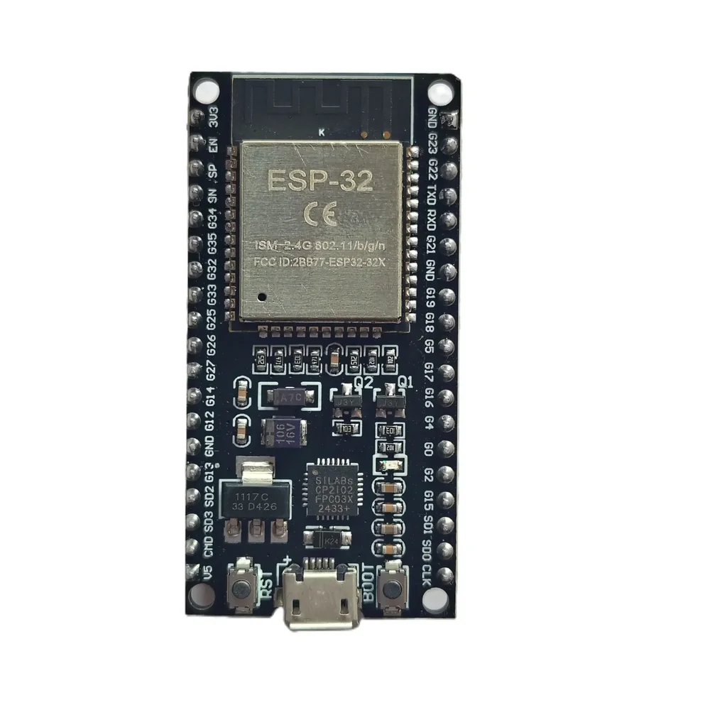
ESP32 38-Pin Development Board – IoT Microcontroller with WiFi & Bluetooth
[ESP Modules] Description The ESP32 38-Pin Development Board is a versatile and cost-effective microcontroller platform perfect for a wide range of IoT, automation, and wireless communication projects. Powered by the ESP32 SoC, this board offers integrated WiFi and Bluetooth (BLE) capabilities, making it ideal for developing smart home devices, industrial control systems, robotics, and DIY electronics. For the best IoT experience, you can pair this board with our LoRa SX1278 Module for long-range communication or integrate it with our 0.96-inch OLED Display for real-time data display. Need reliable power control? Combine it with our 2-Channel Relay Module with Optocoupler for safe switching of external devices. Compatible with popular platforms like Arduino IDE, MicroPython, and PlatformIO, this ESP32 board is user-friendly for both beginners and professionals. The board features 38 GPIO pins, enabling you to connect a variety of sensors, actuators, and other peripherals—available in our IoT Components category. Key Features: ESP32 Dual-Core 32-bit LX6 Processor Built-in 2.4 GHz WiFi and Bluetooth 4.2 (BLE) 38 GPIO Pins supporting multiple digital and analog functions Interfaces: UART, SPI, I2C, PWM, ADC, DAC Ultra-low power operation modes ideal for battery-powered IoT devices Supports Arduino IDE, MicroPython, and other environments Onboard micro-USB connector for easy power and programming Reset and boot buttons for firmware flashing Breadboard-friendly form factor Applications: IoT development projects Smart home automation – compatible with Vihaan IoT Gateway Solutions Wireless data logging systems Robotics and drone controllers Industrial monitoring devices Sensor networks – connect with our DHT11/DHT22 Temperature Sensors Specifications: Chipset: ESP32 (Generic) Operating Voltage: 3.3V (5V tolerant inputs) Flash Memory: 4MB Connectivity: WiFi IEEE 802.11 b/g/n, Bluetooth 4.2 BLE Interfaces: GPIO, UART, SPI, I2C, ADC, DAC, PWM USB Interface: Micro USB Form Factor: 38-Pin, breadboard compatible Package Includes: 1 x ESP32 38-Pin Generic Development Board
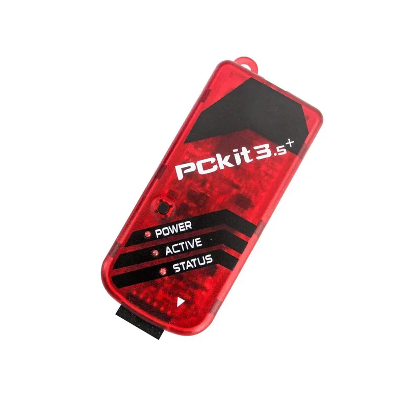
PICKIT3.5 Plus Microchip Programmer W/USB Cable Wires Pic Kit 3.5+
Description: PICKIT3.5 Plus In-Circuit Debugger/Programmer compatible with Microchip uses in-circuit debugging logic incorporated into each chip with Flash memory to provide a low-cost hardware debugger and programmer. The PICKIT3.5 Plus allows debugging and programming of PIC and dsPIC Flash microcontrollers using the powerful graphical user interface of the MPLAB Integrated Development Environment (IDE). PICKIT3.5 Plus is an upgrade from the Pickit 3 programmer with the programming-to-go feature. Specifications: Type: Debugger/Programmer Tool/Board Application: Debugging/Programming MCU Supported Families: Flash-based PIC MCUs Core Architecture: PIC, dsPIC IC Product Type: In-Circuit Debugger Features USB (Full speed 12 Mbits/s interface to host PC) Real-time execution MPLAB IDE compatible (free download from Microchip) Built-in over-voltage/short circuit monitor Firmware upgradeable from PC/web download Diagnostic LEDs (power, busy, error) Read/write program and data memory of the microcontroller Erase of program memory space with verification Freeze-peripherals at breakpoint Program up to 512K byte flash with the Programmer-to-Go ICSP cable included Package Included: 1 x PICKIT3.5 Plus Microchip Programmer W/USB Cable Wires Pic Kit 3.5+
 Out of stock
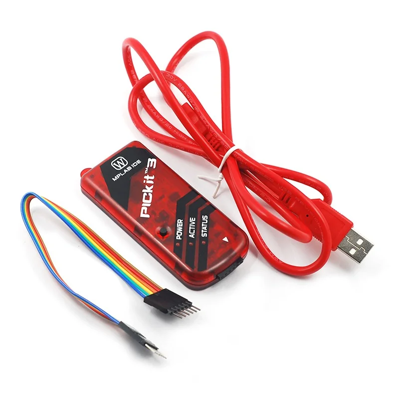
PICkit3 Debugger Programmer Emulator Controller Development Board
[Uncategorized] This is PICkit3 Debugger Programmer Emulator Controller Development board w/ Pinout diagram to ease the customer. The USB connection is more stable than ICD2. PICKIT3.5, begin to support Win7 system. Full patch design, patch through the reflow soldering processing, more stable quality. PIC developing data, C language development tool manual. A lot of PIC basic experiment program code; ICD2 PICKIT3 etc application specification. The MPLAB PICkit 3 allows debugging and programming of PIC® and dsPIC® Flash microcontrollers at a most affordable price point using the powerful graphical user interface of the MPLAB Integrated Development Environment (IDE). The MPLAB PICkit 3 is connected to the design engineer’s PC using a full-speed USB interface and can connect to the target via a Microchip debug (RJ-11) connector (compatible with MPLAB ICD 2, MPLAB ICD 3 and MPLAB REAL ICE). Pickit3 Pinout: Features : Full-speed USB support using Windows standard drivers Real-time execution Processors run at maximum speeds Built-in over-voltage/short circuit monitor Low voltage to 5V (1.8 to the 5V range) Read/write program and data memory of the microcontroller Diagnostic LEDs (power, active, status) Read/write program and data memory of the microcontroller 1Erase of all memory types (EEPROM, ID, configuration, and program) with verification Peripheral freeze at the breakpoint. Program up to 512K byte flash. Package Includes : 1 x PICKIT3 Programmer. 1 x USB cable 1x 6pin cable A DVD
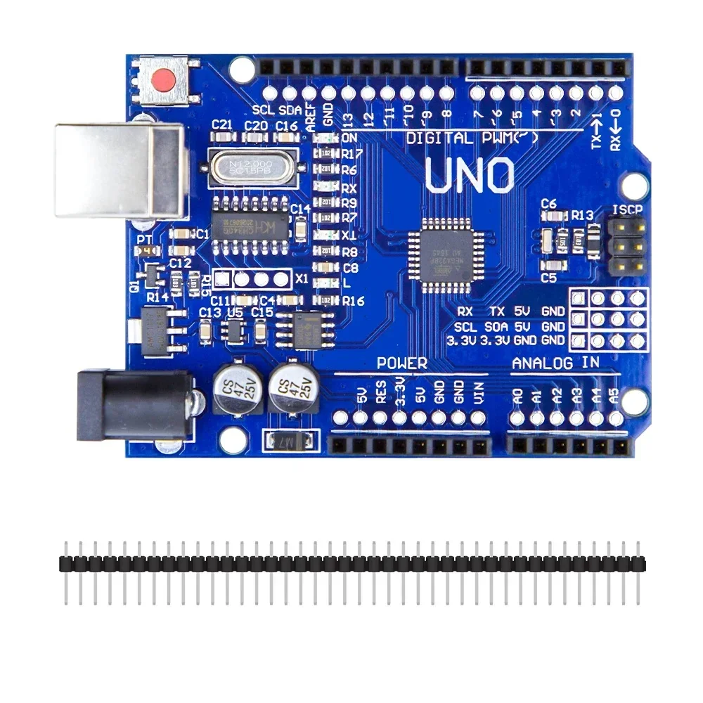
Arduino Uno R3 CH340G ATMega328P Development Board Compatible with Arduino
[Arduino Boards, Development Board] Product Description The Uno R3 CH340G ATmega328p Development Board is the low-cost version of the popular Uno R3 Arduino. It is assembled with the CH340 USB to Serial converter chip, instead of using an Atmega16U2 chip. We have used plenty of these low-cost Arduino boards with CH340 chips, and have found them to work perfectly. The only time the CH340 chip is used is during programming and when using the serial output of the USB port. During normal operation, this board is identical to the more expensive version without CH340 chip. Features The Arduino Uno R3 is a micro-controller board base on the ATmega328 . It has 14 digital input/output pins (of which 6 can be used as PWM outputs); 6 analog inputs, a 16 MHz ceramic resonator, a USB connection, a power jack, an ICSP header, and a reset button. It contains everything need to support the micro-controller; simply connect it to a computer with a USB cable or power it with a AC-to-DC adapter or battery to get start. The Arduino Uno R3 differs from all preceding boards in that it does not use the FTDI USB-to-serial driver chip. Instead, it features the Atmega16U2 (Atmega8U2 up to version R2) program as a USB-to-serial converter. Revision 2 of the Uno board has a resistor pulling the 8U2 HWB line to ground, making it easier to put into DFU mode. Note: The Arduino Uno R3 reference design can use an Atmega8, 168, or 328, Current models use an ATmega328, but an Atmega8 is shown in the schematic for reference. The pin configuration is identical on all three processors. Package Includes 1 x Arduino Uno R3 CH340G ATMega328P Development Board
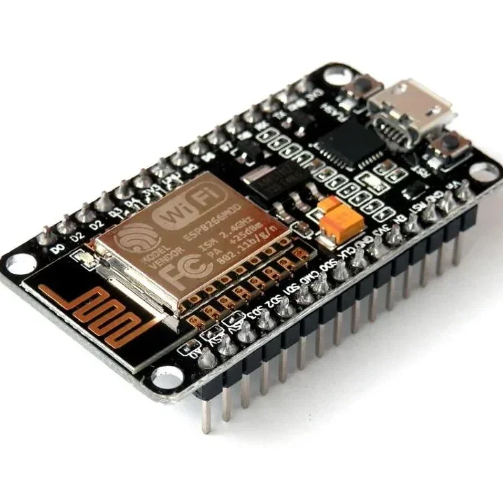
ESP8266 NodeMCU CP2102 ESP-12E WiFi Development Board
[ESP Modules] ESP8266 NodeMCU CP2102 ESP-12E WiFi Development Board ESP8266 ESP-12E • CP2102 USB Interface • Built-in WiFi • Arduino & Lua Compatible • IoT Development Board The ESP8266 NodeMCU CP2102 ESP-12E WiFi Development Board is a compact and powerful development board designed for IoT (Internet of Things), wireless communication, home automation, robotics, and embedded system projects. Based on the highly popular ESP8266 ESP-12E WiFi module, it combines a 32-bit microcontroller, WiFi connectivity, and a CP2102 USB-to-Serial interface on a single breadboard-friendly board. The board comes preloaded with NodeMCU firmware, allowing easy programming using Lua scripting, while also offering full compatibility with the Arduino IDE, making it suitable for both beginners and advanced developers. With integrated 802.11 b/g/n WiFi, TCP/IP networking, multiple GPIO pins, PWM, I2C, SPI, and UART interfaces, it provides everything required for rapid IoT prototyping and wireless application development. The onboard CP2102 USB interface, 3.3V voltage regulator, and logic-level conversion circuitry allow direct connection to a computer for programming and power, eliminating the need for external USB-to-Serial converters. ⭐ Features ESP8266 ESP-12E WiFi module Built-in CP2102 USB-to-Serial interface 802.11 b/g/n WiFi connectivity Integrated TCP/IP protocol stack 32-bit processor with onboard memory Compatible with Arduino IDE, Lua, and NodeMCU firmware Breadboard-friendly compact design Multiple GPIO pins Supports PWM, I2C, SPI, and UART Onboard 3.3V voltage regulator Logic-level conversion circuitry included Low power consumption Ideal for IoT and wireless projects Easy plug-and-play programming 📋 Technical Specifications Product Type: WiFi Development Board Model: ESP8266 NodeMCU ESP-12E Microcontroller: ESP8266EX WiFi Standard: IEEE 802.11 b/g/n USB Interface: CP2102 Operating Voltage: 3.3V Input Voltage: 5V via Micro USB Flash Memory: 4MB CPU: 32-bit Tensilica L106 Clock Frequency: 80MHz / 160MHz GPIO Pins: Multiple Digital I/O Communication Interfaces: UART, SPI, I2C PWM Support: Yes ADC: 1 Channel (10-bit) USB Connector: Micro USB Firmware: NodeMCU (Preloaded) Programming Support: Arduino IDE, Lua, ESP8266 SDK Board Size: Approx. 58 × 31 mm 🔧 Applications IoT (Internet of Things) Projects Home Automation Smart Lighting Systems WiFi Sensor Nodes Wireless Data Logging Robotics Projects Arduino WiFi Projects ESP8266 Development Remote Monitoring Systems MQTT Applications Web Server Projects Smart Agriculture Industrial Automation DIY Electronics Educational Projects 📦 Package Includes 1 × ESP8266 NodeMCU CP2102 ESP-12E WiFi Development Board ⚠️ Note Operates at 3.3V logic levels. Install the CP2102 USB driver if the board is not detected by your computer. Use a good quality Micro USB cable for programming and power. Product appearance may vary slightly depending on the manufacturing batch.
 Out of stock
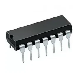
74HC47 or 74LS47 IC BCD to seven segment decoder driver
[Logic Gates IC] 7447 or 74LS47 decodes BCD into 7 Segments, which means it accepts a binary coded decimal or BCD Values as input and decoded into a pattern that drives a 7-segment for displaying digits 0 to 9, so its name is BCD to 7 segment driver or decoder. Its input is 4 lines BCD data and generates complements as output. The generation of complement data of BCD is internally so no coding or programming is required to generate it. Specification Large Voltage range Has open collector output which directly drives indicator Has a wide range of operating conditions No need for external resistors because of internal pull-ups No high-speed termination because of the input clamp diode 4 the number of input lines and 7 output lines Pin Description BCD input 2 BCD input 3 LT RBO RBI BCD input 4 BCD input 1 GND E D C B A G F VCC
 Out of stock
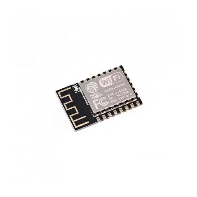
ESP-12F ESP8266 Wifi Wireless IoT Board Module
[ESP Modules] The ESP-12F ESP8266 WiFi Module is a powerful and low-cost WiFi transceiver module designed for Internet of Things (IoT) applications. Built around the ESP8266 SoC, this module integrates a full TCP/IP protocol stack, enabling microcontrollers to connect directly to WiFi networks. With its integrated 32-bit RISC processor, on-chip memory, and multiple communication interfaces, the ESP-12F module can either host an application independently or act as a WiFi adapter for another microcontroller such as Arduino, Raspberry Pi, or STM32. Each module is typically shipped with AT command firmware, allowing easy communication through UART serial interface. This means developers can quickly add WiFi functionality to existing hardware without complex programming. The ESP-12F version improves performance compared to earlier modules by offering: Stronger WiFi signal output Improved anti-interference capability Optimized PCB antenna design Better impedance matching The module supports station mode, soft-AP mode, and combined AP + station mode, making it highly versatile for IoT networking. Because of its high integration, small size, and low power consumption, the ESP-12F module is widely used in: IoT devices Home automation systems Smart appliances Wireless sensor networks Industrial monitoring systems ⭐ Key Features Based on ESP8266 SoC Built-in TCP/IP protocol stack Integrated 2.4GHz WiFi Supports Station / SoftAP / Station + AP modes Pre-programmed AT command firmware Compact SMD design Strong PCB antenna Low power consumption Multiple communication interfaces 🔧 Technical Specifications Model: ESP-12F Chipset: ESP8266 WiFi Standard: IEEE 802.11 b/g/n Frequency: 2.4 GHz Operating Voltage: 3.3V Maximum Current: ~240mA Standby Power: < 1mW Interface: UART / SPI / SDIO Baud Rate: 115200 (default) Communication Format: 8N1 Security: WPA / WPA2 Package Type: 32-Pin QFN Output Power: +19.5 dBm 📡 Supported Interfaces UART SPI SDIO 1.1 / 2.0 I2S (audio interface) Multiple GPIO pins 🎯 Applications IoT projects Smart home automation Wireless sensor networks Arduino WiFi connectivity Remote monitoring systems Industrial IoT applications 📦 Package Includes 1 × ESP-12F ESP8266 WiFi Module
 Out of stock
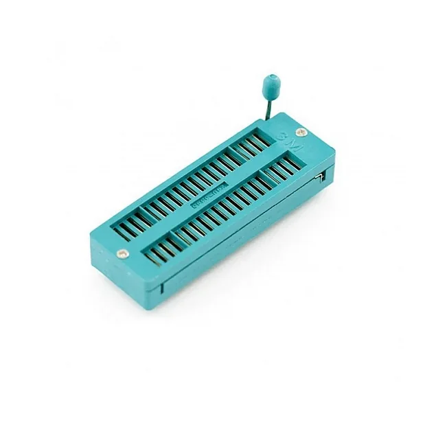
40 Pin ZIF Socket Base
[IC Base] ZIF socket stands for Zero Insertion Force. This socket works as a test Board for IC. The device is incorporated with a lever actuator, which reduces the damage of IC leads during insertion and withdrawal, perfect test, burn-in, and programming of a dual-in-line package (DIP). It is perfect for use with ICs that require frequent changing and it comes with an armature that can be used to lock and unlock the IC to the base. Features: Ideal for programming and testing. Suitable for ICs up to 40 pins. Low contact resistance when the IC is in place. Lever action for easy insertion and removal. Package Includes: 1 x 40 Pin ZIF Socket Base.
 Out of stock
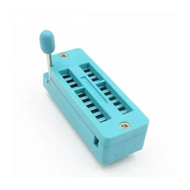
20 Pin ZIF Socket Base
[IC Base] ZIF socket stands for Zero Insertion Force. This socket works as a test Board for IC. The device is incorporated with a lever actuator, which reduces the damage of IC leads during insertion and withdrawal, perfect test, burn-in, and programming of a dual-in-line package (DIP). It is perfect for use with ICs that require frequent changing and it comes with an armature that can be used to lock and unlock the IC to the base. Features: Ideal for programming and testing. Suitable for ICs up to 20 pins. Easy to Remove and Program IC's Nickel-Tin Plated Contacts Low contact resistance when the IC is in place. Lever action for easy insertion and removal. Package Includes: 1 x 20 Pin ZIF Socket Base.
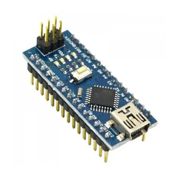
Nano CH340 Chip Board without USB cable compatible with Arduino (Soldered)
[Arduino Boards] 🔷 Nano V3 CH340 ATmega328P Development Board (Soldered Headers) Compatible with Arduino ATmega328P • CH340 USB Interface • Compact Design • Breadboard Friendly • Ready to Use The Nano V3 CH340 Development Board is a compact and powerful microcontroller board based on the ATmega328P-AU microcontroller. Fully compatible with the Arduino Nano platform, it offers the same functionality as the Arduino Uno in a much smaller, breadboard-friendly form factor, making it ideal for embedded systems, robotics, IoT, automation, and DIY electronics projects. This version features the CH340 USB-to-Serial converter, providing a cost-effective and reliable programming interface. The board comes with pre-soldered headers, allowing it to be plugged directly into a breadboard or PCB without additional soldering. Powered by the ATmega328P running at 16MHz, the Nano provides 14 digital I/O pins, 8 analog input pins, 6 PWM outputs, and supports communication protocols including UART, SPI, and I²C. The onboard bootloader allows programming directly through the Mini USB port using the Arduino IDE. The Nano can be powered through the Mini USB connector, an external 6–20V DC supply, or a regulated 5V input, with automatic power source selection for seamless operation. Note: Some computers may require the CH340 USB driver before the board is recognized. ⭐ Features Based on ATmega328P-AU microcontroller Compatible with Arduino Nano V3 CH340 USB-to-Serial interface Pre-installed Arduino bootloader Pre-soldered header pins Compact breadboard-friendly design 14 Digital I/O pins (6 PWM) 8 Analog input pins 16MHz crystal oscillator Mini USB interface for programming Automatic power source selection Manual reset button ICSP header for direct programming TX, RX, Power and L status LEDs Supports Arduino IDE 📋 Technical Specifications Product Type: Microcontroller Development Board Board Version: Nano V3 Microcontroller: ATmega328P-AU USB Interface: CH340G Operating Voltage: 5V Input Voltage (Recommended): 7V–12V DC Input Voltage Range: 6V–20V DC Digital I/O Pins: 14 PWM Channels: 6 Analog Input Pins: 8 Flash Memory: 32KB SRAM: 2KB EEPROM: 1KB Clock Speed: 16MHz USB Connector: Mini USB Communication Interfaces: UART, SPI, I²C Programming: Arduino IDE Bootloader: Pre-installed Board Dimensions: 43 × 18 mm Mounting: Breadboard Compatible 🔧 Applications Suitable for: Arduino Projects Robotics IoT Devices Home Automation Sensor Interfaces Embedded Systems Educational Projects Industrial Automation Data Logging LED Control Motor Control Smart Home Devices Wearable Electronics DIY Electronics Rapid Prototyping 📦 Package Includes 1 × Nano V3 CH340 ATmega328P Development Board (Soldered Headers) USB Cable Not Included ⚠️ Note Mini USB cable is not included. Some Windows computers may require the CH340 USB driver before programming the board. Compatible with the Arduino IDE after selecting Arduino Nano and the appropriate processor/bootloader settings. Product appearance, PCB color, and component layout may vary slightly depending on the manufacturing batch.
 Out of stock
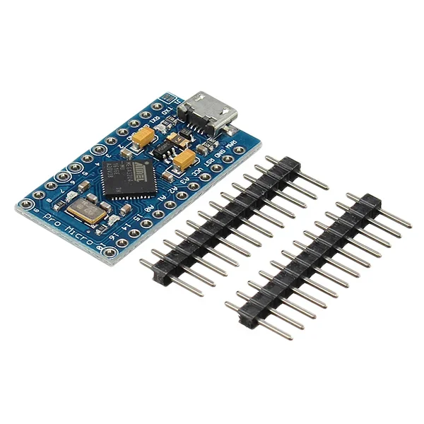
Pro Micro 5V 16M Mini Leonardo Microcontroller Development Board For Arduino
[Arduino Boards] This Pro Micro 5V 16M Mini Leonardo Microcontroller Development Board For Arduino development board has 4 channel 10 bit ADC, 5 PWM pins, 12 DIO, and a hardware serial connection Rx and Tx you are familiar with Running on 16MHz and 5V, this board will remind you a lot of other Arduino compatible boards that you like. There is a voltage regulator on board, so it can accept up to 12V DC. The Micro is a microcontroller board based on the ATmega32U4. It has 20 digital input/output pins (of which 7 can be used as PWM outputs and 12 as analog inputs), a 16 MHz crystal oscillator, a micro USB connection, an ICSP header, and a reset button. It contains everything needed to support the microcontroller; simply connect it to a computer with a micro USB cable to get started. It has a form factor that enables it to be easily placed on a breadboard. The Micro board is similar to the Arduino Leonardo in that the ATmega32U4 has built-in USB communication, eliminating the need for a secondary processor. This allows the Micro to appear to a connected computer as a mouse and keyboard, in addition to a virtual (CDC) serial / COM port. If you supply an unstable power supply board, be sure to connect to the “RAW”, not on the VCC pin. It has also added a PTC fuse and diode protection to the power circuit and to correct the RX and LED TX circuits. Features : ATMEGA32U4 running in 5V / 16MHz Support Arduino IDE V1.0.1 Micro USB interface programming on the board Four 10-bit ADC pin 12 digital I / O (5 PWM capability) Rx and Tx hardware serial connection. Pin Diagram: Package Includes : 1 x Pro Micro 5V 16M Mini Leonardo Microcontroller Development Board For Arduino
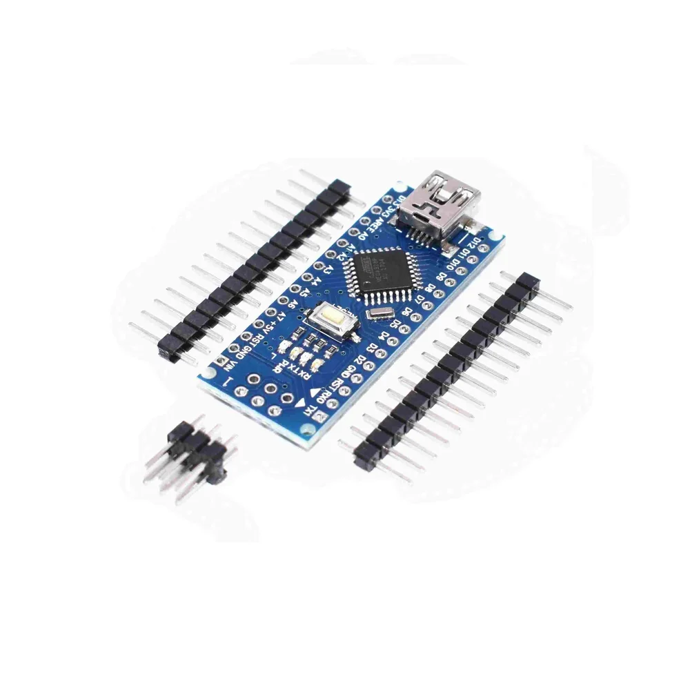
Nano Board R3 with CH340 chip without USB Cable compatible with Arduino (Unsoldered)
[Arduino Boards] The Nano Board R3 with CH340 chip without USB Cable chipboard is based on the famous Arduino platform and does all the functions of Uno, but with a smaller footprint. The Nano Board R3 with CH340 chip without USB Cable is vital for your small project where you don’t need much of a pin-outs but the small size is very important to make it look good. This Nano equips a low-cost USB-Serial Chip that makes it less in price than Nano with FTDI USB-Serial Chip used on older versions of Arduino Nano. The Nano Arduino is a small, complete, and breadboard-friendly board based on the ATmega328 (Nano R3). It has more or less the same functionality of the Uno but in a different package. It lacks only a DC power jack and works with a Mini-B USB cable instead of a standard one. The Nano can be power via the mini-USB connection, 6-20V unregulated external power supply (pin 30), or 5V regulated external power supply (pin 27). The power source is automatically selected to the highest voltage source. The size of Nano V3.0 with CH340 Chip is only 43 mm x 18 mm; it comes with 6 PWM I/O from the total of 14 digitals I/O, 8 analog inputs, 16Mhz clock speed and 32kB of flash memory. Note:- CH340 chip might not work directly with some PC/Laptop, you will need some ch340 drivers. This board comes with OLD BOOTLOADER buy it accordingly Features : 1 pair of TTL level serial transceiver ports RX / TX Using Atmel Atmega328P-AU MCU There is a bootloader installed in it Support USB download and Power Support for external 5V ~ 12V DC power supply It Supports power supply by 9V battery Support ISP download Automatic reset during program download. Power OK blue LED on the bottom. Green (TX), red (RX) and orange (L) LED. +5V to AREF jumper. Auto-sensing/switching power input. Small mini-B USB for programming and serial monitor. ICSP header for direct program download. Standard 0.1” spacing DIP (breadboard friendly). Manual reset switch. Package Includes : 1 x Nano Board R3 with CH340 chip without USB Cable compatible with Arduino (Unsoldered)
 Out of stock
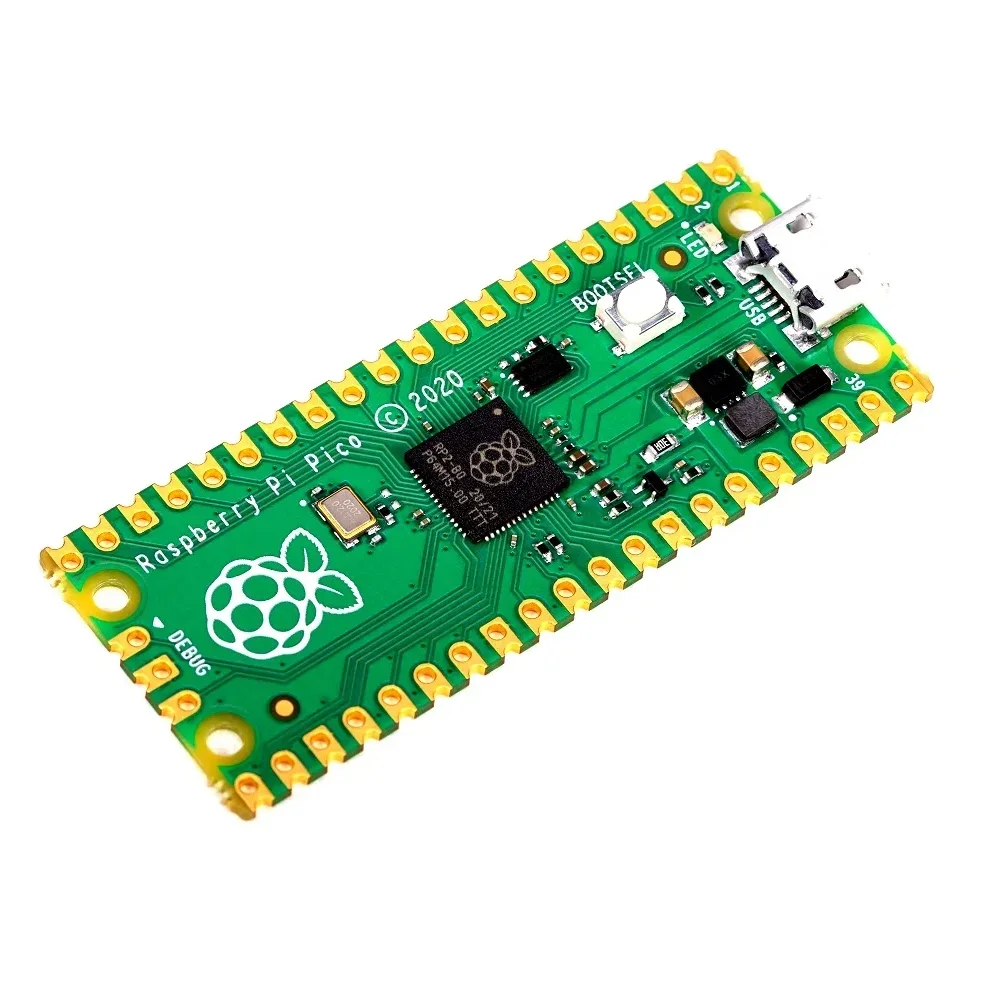
Raspberry Pi Pico Original Version Dual-core Arm Cortex
[Raspberry Pi] Raspberry Pi Pico Original Version Dual-core Arm Cortex Description: Almost one and half-year before Raspberry had launched a revolutionary update on their Single Board Computer (SBC) Pi 3 and become the most popular Microcontroller board in the community which is known as a Raspberry pi 4. On the same timeline, the Raspberry pi foundation came with a new astonishing SBC named a Raspberry Pi PICO. The main highlighted thing about RPI PICO it is the Lowest cost and Smallest size development board from Raspberry pi Foundation. On the technical side, it is equipped with an RP2040 Microcontroller chip developed by Raspberry Pi Foundation itself. RP400 is their first dual-core ARM Cortex M0+ processor-based latest small-sized, budget-friendly microcontroller. The RP2040 is supported with both c / c ++ and micro-python, meaning that if you’re a beginner and want to learn any of these languages, the Raspberry Pico would be the best product-option to start with. Key Features 21 mm x 51 mm form factor RP2040 microcontroller chip designed by Raspberry Pi in the UK Dual-core Arm Cortex-M0+ processor, the flexible clock running up to 133 MHz 264KB on-chip SRAM 2MB onboard QSPI Flash 26 multifunction GPIO pins, including 3 analog inputs 2 x UART, 2 x SPI controllers, 2 x I2C controllers, 16 x PWM channels 1 x USB 1.1 controller and PHY, with host and device support 8 x Programmable I/O (PIO) state machines for custom peripheral support Supported input power 1.8-5.5V DC Operating temperature -20C to +85C The castellated module allows soldering directly to carrier boards Drag-and-drop programming using mass storage over USB Low-power sleep and dormant modes Accurate on-chip clock Temperature sensor Accelerated integer and floating-point libraries on-chip Package Content 1 X Raspberry Pi Pico
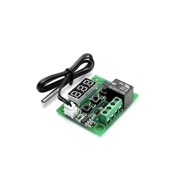
W1209 Digital Temperature Controller Thermostat Module with Display and Waterproof Temperature Sensor
[Temperature Sensor] XH W1209 12V Digital Temperature Control Module + Display and NTC Temp Sensor This is XH W1209 digital temperature controller Module W/ Display and NTC Waterproof Temperature Sensor. W1209 Mini thermostat Temperature controller is low-cost 12V Temperature controller with 7-segment display and 3 switch keypad for setting temperature and other parameters. The module features an NTC thermistor temperature sensing and has an accuracy of 0.1 C. The XH W1209 digital temperature controller Module W/ Display and NTC Waterproof Temperature Sensor is an incredibly low cost yet highly functional thermostat controller. With this module, you can intelligently control power to most types of electrical device based on the temperature sensed by the included high accuracy NTC temperature sensor. Although this module has an embedded microcontroller no programming knowledge is required. 3 tactile switches allow for configuring various parameters including on & off trigger temperatures. The onboard relay can switch up to a maximum of 240V AC at 5A or 14V DC at 10A. We can display current temperature in degrees Centigrade via its 3 digit seven segment display and the current relay state by an onboard LED. DISPLAYING THE CURRENT TEMPERATURE The thermostat will display the current temperature in °C by default. When in any other mode making no input for approximately 5 seconds will cause the thermostat to return to this default display. SETTING THE TRIGGER TEMPERATURE To set the trigger temperature press the button marked ‘SET’. The seven-segment display will flash. You can now set a trigger temperature (in °C) using the ‘+’ and ‘-‘ buttons in 0.1° increments. If we didn’t press any buttons for approximately 2 seconds the trigger temperature will be store and the display will return back to the current temperature. SETTING THE PARAMETERS To set any parameter first long press the ‘SET’ button for at least 5 seconds. The seven-segment display should now display ‘P0’. This represents parameter P0. Pressing the ‘+’ or ‘-‘ buttons will cycle through the various parameters (P0 to P6). Pressing the ‘SET’ button whilst any of these parameters are displayed will allow you to change the value for that parameter using the ‘+’ and ‘-‘ buttons. When finished setting a parameter press the set button to exit that option. If no buttons are pressed for approximately 5 seconds the thermostat will exit the parameter options and will return back to the default temperature display. SETTING THE COOLING OR HEATING PARAMETER P0 The parameter P0 has two settings, C and H. When setting to C (default) the relay will energize when the temperature is reached. Use this setting if connecting to an air-conditioning system. When set to H the relay will de-energize when the temperature is reached. Use this setting if controlling a heating device. SETTING THE HYSTERESIS PARAMETER P1 This sets how much change in temperature must occur before the relay will change state. For example, if set to the default 2oC and the trigger temperature has been set to 25oC, it will not de-energize until the temperature falls back below 23oC. Setting this hysteresis helps stop the thermostat from continually triggering when the temperature drifts around the trip temperature. SETTING THE UPPER LIMIT OF THE THERMOSTAT PARAMETER P2 This parameter limits the maximum trigger temperature that can be set. It is useful as a safety to stop an excessively high trigger temperature from accidentally being set by the user. SETTING THE LOWER LIMIT OF THE THERMOSTAT PARAMETER P3 This parameter limits the minimum trigger temperature that can be set. It is useful as a safety to stop an excessively low trigger temperature from accidentally being set by the user. SETTING TEMPERATURE OFFSET CORRECTION PARAMETER P4 Should you find there is a difference between the displayed temperature and the actual temperature; (for instance, if the temperature probe is on a long run of cable) you can make minor corrections to the temperature reading with this parameter. SETTING THE TRIGGER DELAY PARAMETER P5 To reach trigger temperature this parameter allows for delaying switching of the relay. The parameter can be set in one-minute increments up to a maximum of 10 minutes. SETTING THE HIGH-TEMPERATURE ALARM PARAMETER P6 Setting a value for this parameter will cause the relay to switch off when the temperature reaches this setting. The seven-segment display will also show ‘—‘ to indicate an alarm condition. The relay will not re-energize until the temperature falls below this value. The default setting is OFF.
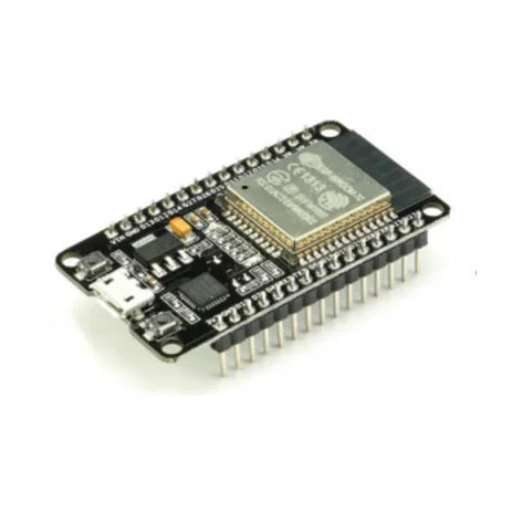
ESP32 Development Board with WiFi and Bluetooth CH9102
[ESP Modules] The ESP32 Development Board – 30 Pin is a powerful and feature-rich microcontroller platform designed for modern IoT and wireless applications. It combines high processing performance with integrated WiFi and Bluetooth connectivity for smart electronic projects. In addition, the board features a dual-core 32-bit LX6 processor running at up to 240MHz. As a result, it can efficiently handle multitasking, wireless communication, and real-time applications. Because of its built-in 2.4GHz WiFi and Bluetooth support, the ESP32 board can communicate with smartphones, cloud platforms, sensors, and other wireless devices. Furthermore, the compact 30-pin layout provides multiple GPIO pins while remaining breadboard compatible. The board supports popular communication protocols such as UART, SPI, I2C, PWM, ADC, and DAC. Therefore, it is suitable for a wide range of embedded and electronics projects. Moreover, the onboard CH9102 USB-to-Serial interface provides stable programming and reliable USB communication. This makes firmware uploading and serial monitoring simple and convenient using platforms such as Arduino IDE, ESP-IDF, and MicroPython. Thanks to its low-power modes and wireless capabilities, the ESP32 development board is widely used in home automation, robotics, industrial monitoring, smart devices, and IoT systems. 🔹 Key Features Dual-core 32-bit LX6 microprocessor Built-in WiFi and Bluetooth (BLE + Classic) Compact 30-pin development board Multiple GPIO pins for interfacing Supports ADC, DAC, PWM, SPI, I2C, and UART Built-in PCB antenna for wireless communication CH9102 USB-to-Serial interface Low power consumption with sleep modes Breadboard-compatible design 🔹 Technical Specifications Chipset: ESP32 Microcontroller: Tensilica Xtensa Dual-Core 32-bit LX6 Clock Speed: Up to 240MHz Flash Memory: 4MB SRAM: 520KB WiFi Standard: IEEE 802.11 b/g/n Bluetooth Version: v4.2 (Classic + BLE) GPIO Pins: 30 USB Interface: CH9102 Operating Voltage: 3.3V Logic Input Voltage: 5V via USB Mounting Type: Breadboard Compatible 🔹 Applications This ESP32 board is suitable for many electronics and wireless applications, including: IoT projects Smart home automation Robotics systems Wireless sensor networks Industrial monitoring systems WiFi-controlled devices Bluetooth communication projects DIY electronics projects 🔹 Package Includes 1 × ESP32 Development Board – 30 Pin * Product Images are shown for illustrative purposes only and may differ from actual product.