
All products · 52 of 1440
Electronics, sensors, robotics kits, PC components, peripherals — everything Unik Systems carries, in one place.
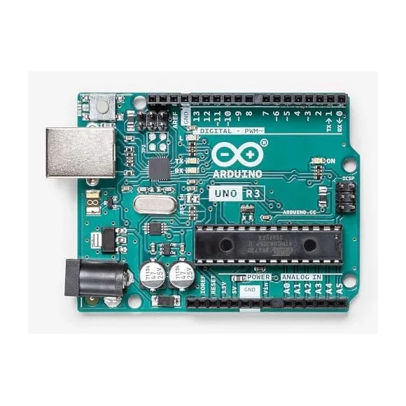
Arduino UNO
Hardware development board (SMD/DIP). ATmega328P, 14 digital I/O, 6 analog, USB-B.
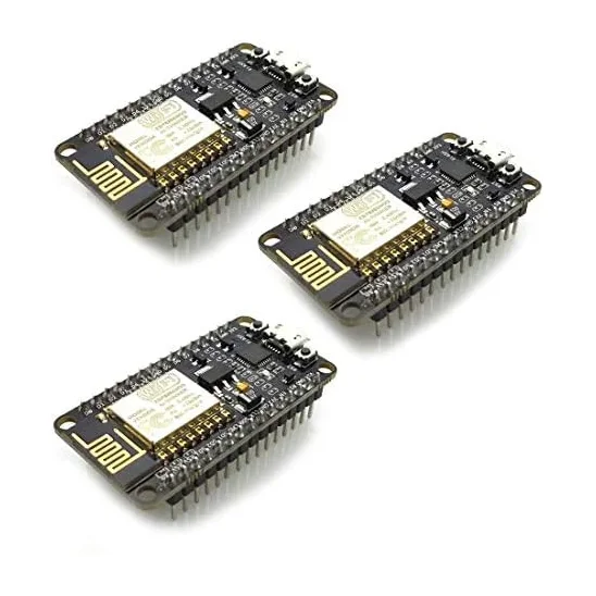
Quarky
Educational STEM controller board. USB programmable. Block coding + Python/Arduino-like. Built-in sensors (mic, light, IMU) + ports for external sensors/servos. 5V input (USB/power bank). BLE/Wi-Fi optional depending on version.
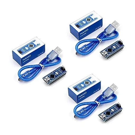
Arduino Nano
Compact development board. ATmega328P, mini-USB. Breadboard friendly.
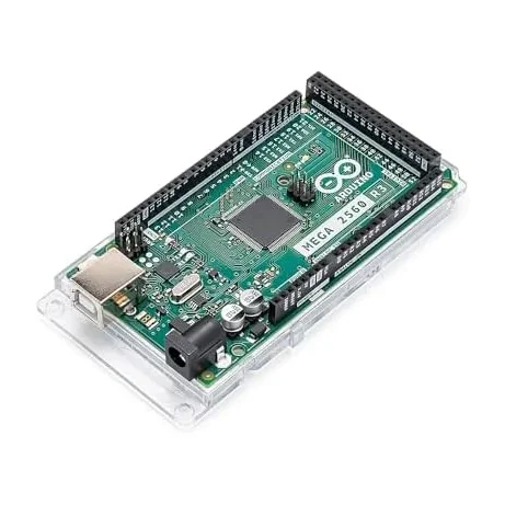
Arduino Mega
Development board. ATmega2560, 54 digital I/O, 16 analog, perfect for big projects.
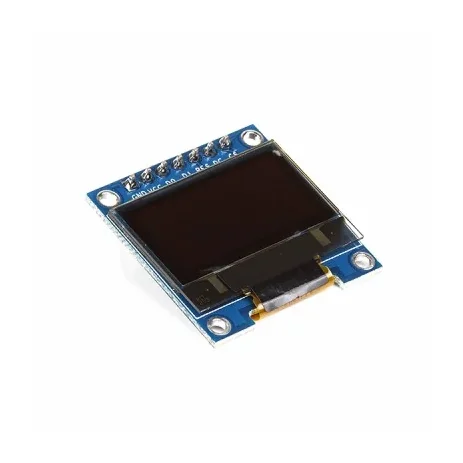 Out of stock
0.96 Inch Blue SPI OLED Display Module 7-Pin 128×64 – SSD1306
[LED/LCD Display] 0.96 Inch Blue SPI OLED Display Module 7-Pin 128×64 – SSD1306 The 0.96-inch Blue OLED Display Module is a compact graphical display based on the SSD1306 driver IC, featuring a 128×64 pixel resolution and blue monochrome display. This version has a 7-pin interface with a dedicated CS (Chip Select) pin, making it suitable for 4-wire SPI communication. The module is factory-configured for SPI and can also be modified for I2C/IIC communication on compatible board versions. With its compact size, wide viewing angle and low-power OLED technology, it is suitable for Arduino, ESP32, ESP8266, STM32, Raspberry Pi and other microcontroller projects. ⭐ Key Features 0.96-inch blue OLED display 128 × 64 pixel resolution SSD1306 driver IC 7-pin interface Dedicated CS (Chip Select) pin Factory configured for 4-wire SPI Supports SPI and I2C/IIC with appropriate configuration 3.3V/5V compatible on supported module versions No backlight required Low power consumption Wide viewing angle of more than 160° Compact PCB design Pre-soldered 7-pin male header Compatible with Arduino, ESP32, ESP8266, STM32 and Raspberry Pi projects 📋 Technical Specifications Display Type: OLED (Organic Light-Emitting Diode) Display Colour: Blue Display Size: 0.96 inch Driver IC: SSD1306 Resolution: 128 × 64 pixels Interface: SPI / I2C Default Interface: 4-wire SPI Input Voltage: 3.3V–5V Viewing Angle: >160° Module Dimensions: Approximately 27 × 27 × 4mm Operating Temperature: Approximately -30°C to +70°C Header: 7-pin male header, pre-soldered Display Type: Monochrome blue OLED 🔌 7-Pin Interface The 7-pin version provides the following connections: GND – Ground VCC – Power supply D0 / SCK / CLK – SPI clock D1 / MOSI / SDA – SPI data RES / RST – Display reset DC / A0 – Data/Command selection CS – Chip Select 🛠️ SPI Connection The module is normally supplied in 4-wire SPI configuration. For an Arduino Uno, a typical connection is: VCC → 5V GND → GND D0 → SCK / D13 D1 → MOSI / D11 RES → Digital I/O DC → Digital I/O CS → Digital I/O The dedicated CS pin allows the OLED to share the SPI bus with other devices such as SD cards or additional SPI peripherals. 🔄 I2C / IIC Configuration On compatible versions, the module can be converted from SPI to I2C by changing the appropriate resistor configuration on the PCB. The supplied board configuration may require: Moving the resistor from R3 to R1 Shorting R8 with solder Using D0 as SCL Using D1 as SDA Configuring DC for the I2C address The exact resistor positions can vary between board revisions, so check the markings on your particular PCB before modification. 🎯 Applications Arduino projects ESP32 projects ESP8266 projects STM32 development Raspberry Pi projects IoT devices Sensor displays Voltage/current meters Battery monitors Temperature displays Digital clocks Data loggers Portable electronic devices Robotics DIY measuring instruments Embedded systems Menu and status displays 💡 Advantages of OLED OLED technology is self-emissive, meaning the pixels produce their own light and do not require a conventional backlight. This provides high contrast, compact construction and a wide viewing angle while keeping power consumption relatively low. ⚠️ Important Notes This is the 7-pin SPI version, not the 6-pin version. The module is normally configured for SPI communication. Check the PCB labels before connecting the module. Do not exceed the specified supply voltage. Although many versions support 5V operation, the exact voltage tolerance can vary between board revisions. I2C operation may require hardware resistor modification. The actual PCB layout and component markings may vary slightly between production batches. Display colour: Blue. Libraries such as Adafruit SSD1306 and U8g2 can be used with compatible microcontrollers. 📦 Package Includes 1 × 0.96 Inch Blue SPI OLED Display Module
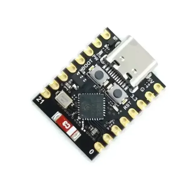
ESP32-C3 Super Mini Development Board With Headers Pins
[ESP Modules] Ultra Compact • Wi-Fi & BLE 5.0 • USB Type-C • Perfect for IoT & Embedded Projects The ESP32-C3 Super Mini Development Board is a compact, feature-rich development board built around the powerful ESP32-C3 SoC from Espressif. Powered by a 32-bit RISC-V single-core processor running at up to 160MHz, it combines 2.4GHz Wi-Fi, Bluetooth 5.0 Low Energy (BLE), and low-power operation in an ultra-small form factor. Designed for IoT, smart home, wireless communication, automation, and embedded system development, the ESP32-C3 Super Mini offers 4MB Flash memory, 400KB SRAM, multiple GPIOs, ADC, PWM, UART, SPI, and I2C interfaces for connecting sensors, displays, relays, and other peripherals. The onboard USB Type-C interface simplifies programming and power supply, while the built-in USB-to-Serial functionality enables quick firmware uploading without requiring additional programmers. Fully compatible with Arduino IDE, ESP-IDF, PlatformIO, and MicroPython, it is suitable for beginners, students, makers, and professional developers. Its ultra-compact breadboard-friendly design makes it ideal for portable and space-constrained projects where performance, wireless connectivity, and energy efficiency are essential. Note: Programming, software configuration, driver installation, firmware flashing, and coding-related issues are not covered under return or replacement. Users are expected to troubleshoot software-related issues independently. ⭐ Features Powerful ESP32-C3 32-bit RISC-V processor CPU frequency up to 160MHz Built-in 2.4GHz Wi-Fi (802.11 b/g/n) Integrated Bluetooth 5.0 Low Energy (BLE) Ultra-compact Super Mini design Breadboard-friendly layout USB Type-C interface for programming and power 4MB onboard Flash memory 400KB SRAM Multiple GPIO, ADC, PWM, UART, SPI & I2C interfaces Low power consumption with Deep Sleep mode Onboard programmable LED Compatible with Arduino IDE, ESP-IDF, PlatformIO & MicroPython Ideal for IoT, automation, robotics, and wireless applications 📋 Technical Specifications Product Type: Development Board Board Model: ESP32-C3 Super Mini Microcontroller: ESP32-C3 Processor Architecture: 32-bit RISC-V CPU Frequency: Up to 160MHz Core: Single Core Flash Memory: 4MB SRAM: 400KB Wi-Fi Standard: IEEE 802.11 b/g/n (2.4GHz) Bluetooth: Bluetooth 5.0 Low Energy (BLE) Operating Voltage: 3.3V Input Voltage: 5V via USB Type-C or 3.3V External USB Interface: USB Type-C GPIO: Multiple Digital GPIO Pins Analog Input: Up to 6 ADC Channels PWM: Supported UART: Supported SPI: Supported I2C: Supported USB-to-Serial: Onboard Onboard LED: User Programmable (GPIO8) Power Consumption: Ultra Low (Deep Sleep ≈ 43µA) Dimensions: Approx. 22.5 × 18 mm Headers: Pre-Soldered 🔧 Applications Suitable for: Internet of Things (IoT) Smart Home Automation Wireless Sensor Networks Home Automation Systems Bluetooth Low Energy Devices Wi-Fi Enabled Controllers Robotics Projects Data Logging Systems Remote Monitoring Industrial Automation Portable Embedded Devices Educational Learning DIY Electronics Projects Wearable Electronics Rapid Prototyping 📦 Package Includes 1 × ESP32-C3 Super Mini Development Board Pin Headers ⚠️ Note Programming, firmware installation, software configuration, and driver-related issues are not covered under warranty, return, or replacement. Please verify board compatibility and install the appropriate development environment before programming. Soldered and non-soldered header pin depend on stock
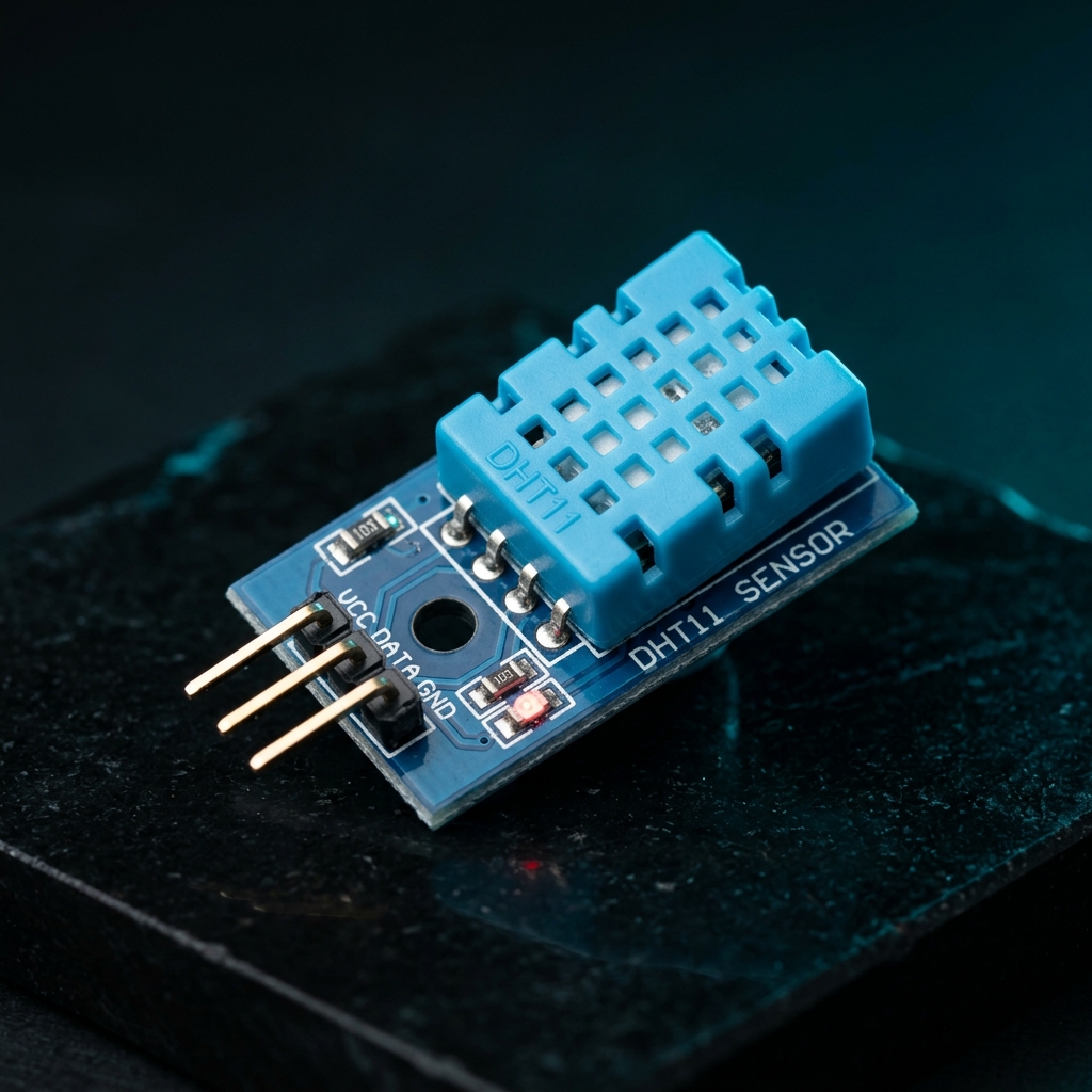
DHT11 Digital Temperature and Humidity Sensor Module 3.3V-5V for Arduino & Raspberry Pi
[Temperature Sensor] The DHT11 Digital Temperature and Humidity Sensor Module is a reliable and cost-effective sensor designed to measure ambient temperature and relative humidity. It combines a capacitive humidity sensing element and a thermistor with a built-in digital signal processing unit, providing calibrated digital output directly to microcontrollers. In addition, the DHT11 offers stable performance and excellent long-term reliability, making it suitable for environmental monitoring and automation applications. As a result, it is widely used in weather stations, smart home systems, greenhouse monitoring, HVAC systems, and educational electronics projects. Because the module includes the required pull-up resistor, interfacing with microcontrollers becomes simple and straightforward. Furthermore, only three connections are required: VCC, GND, and Data Output. The sensor operates from a wide voltage range of 3.3V to 5.5V DC, ensuring compatibility with Arduino, Raspberry Pi, ESP32, STM32, NodeMCU, and other development boards. Moreover, readily available libraries and example codes allow quick integration into projects. The DHT11 utilizes advanced digital signal acquisition technology and dedicated temperature-humidity sensing techniques to ensure accurate and dependable measurements. 🔹 Key Features Measures temperature and humidity simultaneously Calibrated digital signal output Low power consumption High reliability and long-term stability Capacitive humidity sensing technology Built-in pull-up resistor on module Compatible with Arduino, ESP32, Raspberry Pi, and STM32 Simple 3-wire interface Easy integration into IoT projects Compact and lightweight design 🔹 Technical Specifications Sensor Model: DHT11 Operating Voltage: 3.3V – 5.5V DC Output Type: Digital Serial Output Humidity Measurement Range: 20%RH – 90%RH Humidity Accuracy: ±5%RH Humidity Resolution: 1%RH Temperature Measurement Range: 0°C – 50°C Temperature Accuracy: ±2°C Temperature Resolution: 1°C Sampling Rate: 1Hz (One Reading Per Second) Long-Term Stability: < ±1%RH/Year Interchangeability: Fully Interchangeable Sensor Technology: Capacitive Humidity Sensor + Thermistor 🔹 Pin Configuration Pin 1 (VCC): 3.3V – 5.5V DC Power Supply Pin 2 (DATA): Digital Serial Data Output Pin 3 (GND): Ground 🔹 Applications This sensor module is suitable for: Arduino projects Raspberry Pi projects ESP32 projects IoT systems Weather monitoring stations Smart home automation Greenhouse monitoring HVAC control systems Environmental monitoring Educational electronics projects 🔹 Package Includes 1 × DHT11 Digital Temperature and Humidity Sensor Module
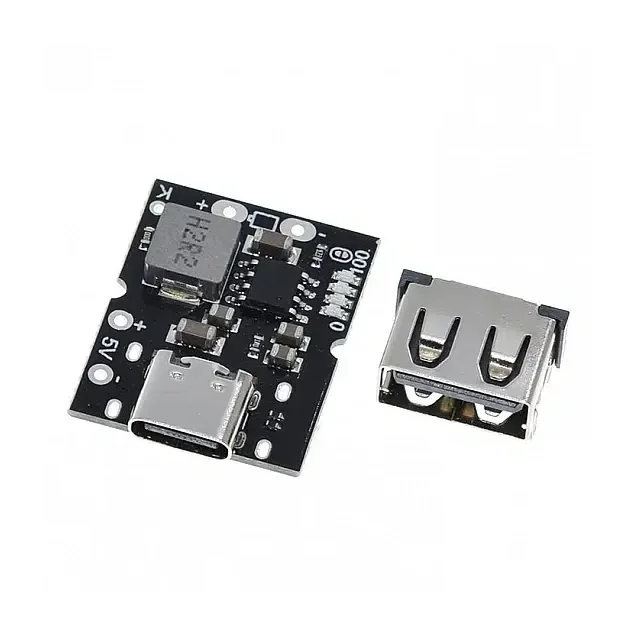
Type-C USB 5V 2A Step-Up Boost Converter with USB Charger
[Li-ion Rechargeable Battery Charger, Step UP Buck Converter] Build your own portable power solutions with the Type-C USB 5V 2A Step-Up Boost Converter Power Bank Module — a compact and efficient charging solution designed for DIY power banks and USB-powered devices. This versatile module supports battery charging and 5V boost output, allowing you to convert battery voltage into a stable 5V USB output for powering smartphones, microcontrollers, and other USB devices. Equipped with a Type-C input, high-efficiency boost circuit, and intelligent power management, this module ensures reliable performance, fast charging, and safe operation. It also supports simultaneous charging and discharging, making it perfect for uninterrupted power supply applications. Key Features 🔋 2-in-1 Charging + Boost ModuleCharge your lithium battery while simultaneously providing a stable 5V output. ⚡ Stable 5V 2A OutputDelivers consistent power for USB devices like smartphones, Arduino, ESP32, and more. 🔌 Type-C USB InputModern and widely compatible input for easy charging (5V–5.5V). 🔄 High Efficiency Boost Conversion (Up to 92.5%)Minimizes power loss and improves battery life. 🧠 Smart Power ManagementAutomatically controls charging cycles, output switching, and battery protection. 🔘 External Button Control Support Short press: Turn ON output & display Double press: Turn OFF output 🔧 DIY Friendly DesignIncludes USB-A solder pads for custom builds and integrations. Working Functions 🔹 Auto shutdown when load current < 50mA🔹 Auto stop charging when current drops to 100mA🔹 Auto recharge when battery voltage < 4.1V🔹 Pre-charge mode below 2.8V (180mA safe charging)🔹 Supports charging while discharging Specifications Specification Description Input Voltage 5V – 5.5V (Type-C USB) Charging Cut-off Voltage 4.2V / 4.35V ±0.5% Charging Current 2.4A ±5% Boost Output Voltage 5V – 5.15V Output Current Up to 2A Efficiency Up to 92.5% Output Ripple 100mV Quiescent Current 30µA Material Metal + Plastic Applications 🔋 DIY Power Banks📱 Mobile Charging Projects🔧 Arduino / ESP32 Power Supply🔌 USB Device Power Modules🚗 Portable Electronics🧪 Embedded Systems & Prototyping Package Includes 1 × Type-C USB 5V 2A Step-Up Boost Converter Power Bank Module
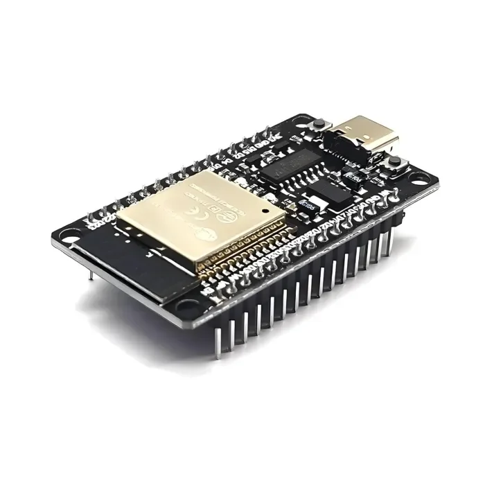
ESP32 Development Board with WiFi & Bluetooth – CH340C USB Type-C
[ESP Modules] The ESP32 Development Board with WiFi & Bluetooth (CH340C, Type-C) is a powerful and versatile microcontroller board designed for modern wireless and IoT applications. It features a dual-core processor and integrated 2.4GHz WiFi and Bluetooth (Classic + BLE) connectivity. This board includes an onboard CH340C USB-to-Serial converter, which allows easy programming and communication without requiring an external crystal oscillator. The USB Type-C port provides a stable and reversible connection for power and data. With a wide range of GPIO pins and peripherals such as ADC, DAC, PWM, UART, SPI, and I2C, this board is perfect for building home automation systems, smart devices, IoT nodes, robotics controllers, sensor networks, web servers, and wireless projects. It is fully compatible with Arduino IDE, ESP-IDF, and MicroPython, making it suitable for beginners, students, and professional developers. 🔹 Key Features Based on ESP32 dual-core microcontroller Built-in WiFi 802.11 b/g/n and Bluetooth v4.2 (Classic + BLE) Onboard CH340C USB-to-Serial converter (no external crystal required) Modern USB Type-C connector for power and programming Dual-core CPU up to 240 MHz for high-performance applications Multiple GPIO pins with ADC, DAC, PWM support Supports Arduino IDE, ESP-IDF, and MicroPython Low-power modes including deep sleep for battery-powered projects Compact design with breadboard-friendly layout Ideal for IoT, automation, robotics, smart home, and DIY electronics 🔹 Technical Specifications Microcontroller: ESP32 CPU: Dual-core Tensilica LX6, up to 240 MHz Flash Memory: 4 MB (typical, may vary by batch) SRAM: 520 KB Wireless Connectivity: WiFi: 2.4 GHz, 802.11 b/g/n Bluetooth: v4.2, Classic + BLE USB Interface: USB Type-C USB-to-Serial Chip: CH340C Operating Voltage: 3.3 V Input Voltage: 5 V via USB Logic Level: 3.3 V GPIO Pins: 30+ multifunction pins Peripherals: ADC, DAC, PWM, UART, SPI, I2C, I2S Clock Frequency: Up to 240 MHz Programming Support: Arduino IDE, ESP-IDF, MicroPython Onboard Components: Reset & Boot buttons, voltage regulator, status LEDs Form Factor: Standard ESP32 Dev Board size 🔹 Applications Internet of Things (IoT) projects Home and industrial automation Smart home devices Robotics and motor control Wireless sensor networks Web servers and cloud-connected devices Educational and training projects DIY electronics and prototyping 🔹 Package Contents 1 × ESP32 Development Board with WiFi & Bluetooth (CH340C, USB Type-C)
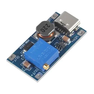
Type-C MT3608 Adjustable Dc to Dc Converter 2-24V to 5V-28V 2A
[Step UP Buck Converter] DC-DC Adjustable Boost Power Supply Module 2V–24V to 5V/9V/12V/28V 2A Type-C The DC-DC Adjustable Boost Power Supply Module is a compact step-up power conversion module designed to increase a lower DC input voltage to a higher adjustable output voltage. It supports a wide 2V–24V input range and provides an adjustable output from approximately 5V to 28V, making it suitable for battery-powered devices, microcontrollers, sensors, portable electronics and DIY power projects. With a compact 30 × 17 × 8mm design and Type-C connector, this module is convenient for projects where space and flexible power input are important. ⭐ Key Features DC-DC boost/step-up converter Wide 2V–24V input voltage range Adjustable output voltage Output options include approximately 5V, 9V, 12V and 28V Maximum output current: 2A Conversion efficiency: >93% Compact and lightweight design Type-C input connector Suitable for battery-powered applications Easy to integrate into DIY electronics projects 📋 Technical Specifications Product Type: DC-DC Boost Converter Module Input Voltage: 2V–24V DC Output Voltage: 5V–28V adjustable Maximum Output Current: 2A Peak Output Current: Up to 2A Efficiency: >93% Input Connector: USB Type-C Product Size: 30 × 17 × 8mm Weight: Approximately 4g Condition: New 🔧 Applications Arduino and microcontroller projects Raspberry Pi and electronic development projects Battery-powered devices Portable power systems GPS and sensor projects LED applications Robotics projects Motors and actuators DIY power supplies Low-voltage to higher-voltage power conversion Portable electronic equipment 🛠️ How It Works This module uses a DC-DC boost conversion circuit to increase the input DC voltage. For example: 3.7V battery → 5V output 5V input → 9V output 5V/12V input → higher adjustable output The required output voltage can be adjusted according to the application. ⚠️ Important Notes This is a boost/step-up module; the output voltage cannot be lower than the applicable input voltage range. Do not exceed the specified 24V maximum input voltage. Do not exceed the 2A maximum output current. Actual maximum output power depends on input voltage, output voltage, cooling and module operating conditions. At higher output power, adequate ventilation/cooling may be required. Always verify the output voltage with a multimeter before connecting sensitive electronics. Do not short-circuit the output. The module does not automatically regulate to 5V/9V/12V/28V; the output must be set to the required voltage. 📦 Package Includes 1 × DC-DC Adjustable Boost Module 2V–24V to 5V/9V/12V/28V, 2A, Type-C
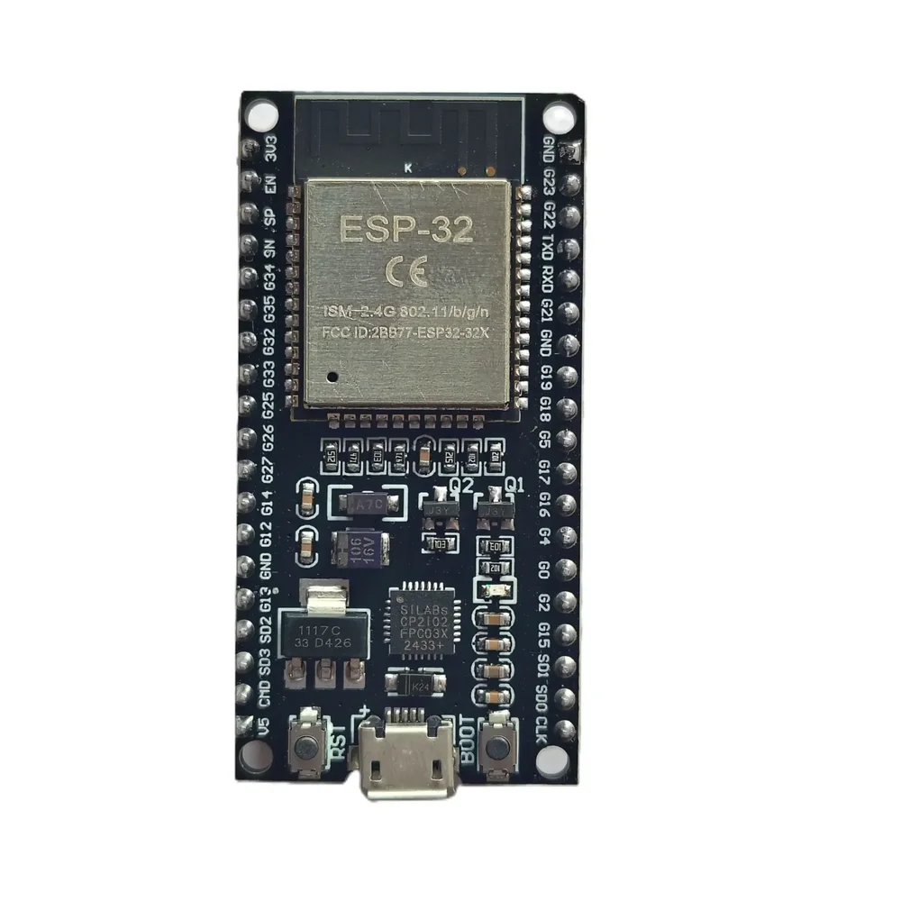
ESP32 38-Pin Development Board – IoT Microcontroller with WiFi & Bluetooth
[ESP Modules] Description The ESP32 38-Pin Development Board is a versatile and cost-effective microcontroller platform perfect for a wide range of IoT, automation, and wireless communication projects. Powered by the ESP32 SoC, this board offers integrated WiFi and Bluetooth (BLE) capabilities, making it ideal for developing smart home devices, industrial control systems, robotics, and DIY electronics. For the best IoT experience, you can pair this board with our LoRa SX1278 Module for long-range communication or integrate it with our 0.96-inch OLED Display for real-time data display. Need reliable power control? Combine it with our 2-Channel Relay Module with Optocoupler for safe switching of external devices. Compatible with popular platforms like Arduino IDE, MicroPython, and PlatformIO, this ESP32 board is user-friendly for both beginners and professionals. The board features 38 GPIO pins, enabling you to connect a variety of sensors, actuators, and other peripherals—available in our IoT Components category. Key Features: ESP32 Dual-Core 32-bit LX6 Processor Built-in 2.4 GHz WiFi and Bluetooth 4.2 (BLE) 38 GPIO Pins supporting multiple digital and analog functions Interfaces: UART, SPI, I2C, PWM, ADC, DAC Ultra-low power operation modes ideal for battery-powered IoT devices Supports Arduino IDE, MicroPython, and other environments Onboard micro-USB connector for easy power and programming Reset and boot buttons for firmware flashing Breadboard-friendly form factor Applications: IoT development projects Smart home automation – compatible with Vihaan IoT Gateway Solutions Wireless data logging systems Robotics and drone controllers Industrial monitoring devices Sensor networks – connect with our DHT11/DHT22 Temperature Sensors Specifications: Chipset: ESP32 (Generic) Operating Voltage: 3.3V (5V tolerant inputs) Flash Memory: 4MB Connectivity: WiFi IEEE 802.11 b/g/n, Bluetooth 4.2 BLE Interfaces: GPIO, UART, SPI, I2C, ADC, DAC, PWM USB Interface: Micro USB Form Factor: 38-Pin, breadboard compatible Package Includes: 1 x ESP32 38-Pin Generic Development Board
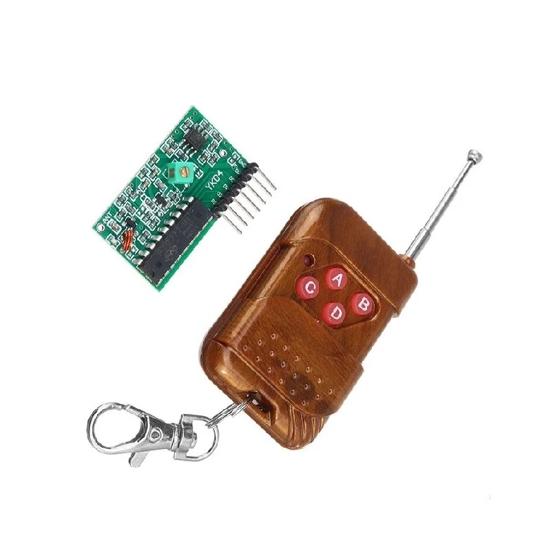
315MHz 4 Channel Wireless RF Remote Control Kit with Receiver Module (Non-Locking Mode)
[RF Module] 📡 315MHz 4 Channel Wireless RF Remote Control Kit with Receiver Module (Non-Locking Mode) 4 Channel RF Remote • 315MHz ASK Communication • 5V Receiver • Non-Locking Mode • Long Range Wireless Control The 315MHz 4 Channel Wireless RF Remote Control Kit is a reliable wireless control solution consisting of a 4-button RF transmitter and a super regenerative ASK receiver module. Operating at 315MHz, this kit is ideal for remote switching, automation, robotics, security systems, and DIY wireless control projects. The receiver module features four independent digital outputs (D0–D3) that correspond to the four buttons on the transmitter. When a button is pressed, the respective output pin goes HIGH, returning LOW immediately after the button is released. This Non-Locking (Momentary/Jog) operation makes the module perfect for applications requiring temporary switching such as electric door control, motor jogging, relay activation, and microcontroller interfacing. The receiver operates from a 5V DC supply and features a high-sensitivity ASK receiver with a Valid Transmission (VT) output pin for reliable signal detection. The transmitter uses a fixed-code encoder for secure communication and easy operation. Ideal for Arduino, ESP32, Raspberry Pi, AVR, PIC, industrial automation, wireless switching, and educational electronics projects. ⭐ Features 4-channel wireless RF remote control kit Operating frequency: 315MHz ASK (Amplitude Shift Keying) modulation Fixed-code RF transmitter Non-Locking (Momentary/Jog) operating mode Four independent digital outputs (D0–D3) High-sensitivity super regenerative receiver 5V DC receiver operating voltage VT (Valid Transmission) status output Compact PCB design Easy interface with microcontrollers Long wireless transmission range (environment dependent) Suitable for DIY and industrial automation 📋 Technical Specifications RF Transmitter Product Type: RF Wireless Remote Control Operating Frequency: 315MHz Number of Buttons: 4 Channels: 4 Modulation: ASK (Amplitude Shift Keying) Encoding Type: Fixed Code Operating Mode: Non-Locking (Momentary) Power Supply: 12V A23 Battery (Not Included) RF Receiver Module Operating Voltage: 5V DC Operating Frequency: 315MHz Receiver Type: Super Regenerative ASK Receiver Receiver Sensitivity: -98dBm Output Channels: D0, D1, D2, D3 VT Output: Yes (Valid Signal Output) Antenna Connection: External ANT Pin Recommended Antenna Length: Approx. 17cm (Quarter-Wave) Module Dimensions: Approx. 41 × 22 × 7 mm Receiver Pin Configuration VT – Valid Signal Output D3 – Channel 4 Output D2 – Channel 3 Output D1 – Channel 2 Output D0 – Channel 1 Output +5V – Power Input GND – Ground ANT – External Antenna Connection 🔧 Operating Modes Non-Locking (Momentary/Jog Mode) Press a button → Corresponding output goes HIGH. Release the button → Output immediately returns LOW. Ideal for momentary control applications. Note: This product is supplied in Non-Locking Mode only. 🔧 Applications Suitable for: Arduino Projects ESP32 Projects Raspberry Pi Projects Wireless Relay Control Home Automation Industrial Automation Remote Door Control Electric Door Locks Wireless Switching Robotics Motor Control Lighting Control Alarm Systems Security Systems DIY Electronics Educational Projects 📦 Package Includes 1 × 4-Button 315MHz RF Wireless Remote Control 1 × 315MHz Super Regenerative Receiver Module ⚠️ Note Battery is included. A 12V A23 battery is required for operation. Avoid bending or touching the receiver's onboard inductor (copper coil), as this may affect receiver sensitivity. Wireless operating range depends on antenna quality, obstacles, and surrounding RF interference. Product appearance may vary slightly depending on the manufacturing batch.
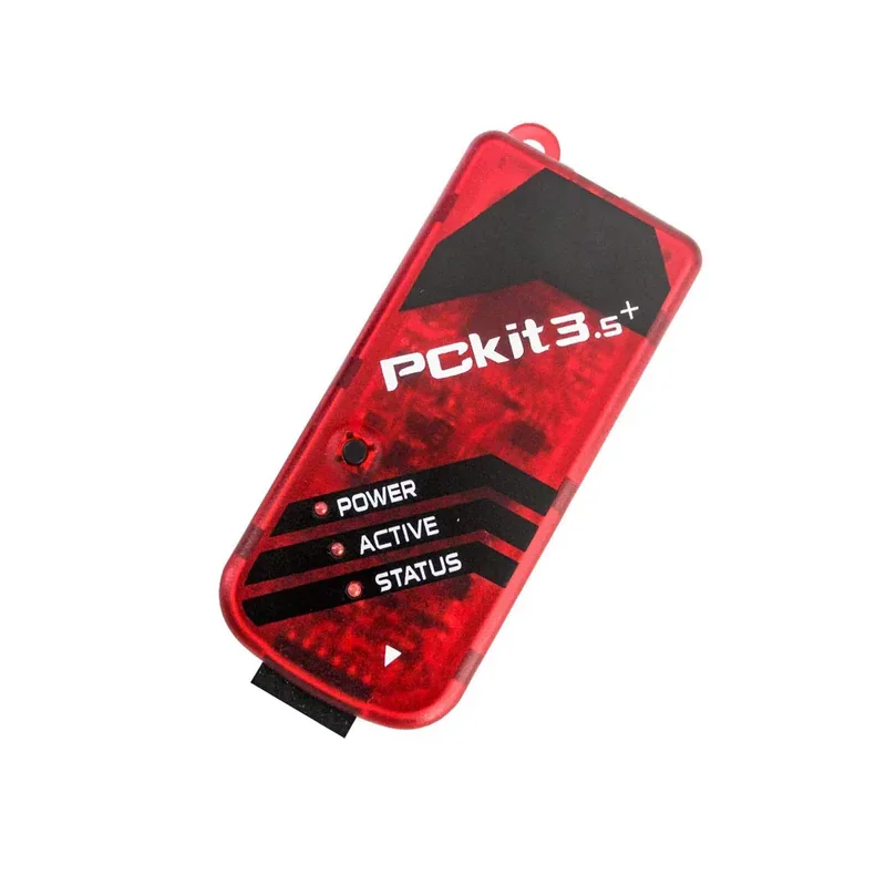
PICKIT3.5 Plus Microchip Programmer W/USB Cable Wires Pic Kit 3.5+
Description: PICKIT3.5 Plus In-Circuit Debugger/Programmer compatible with Microchip uses in-circuit debugging logic incorporated into each chip with Flash memory to provide a low-cost hardware debugger and programmer. The PICKIT3.5 Plus allows debugging and programming of PIC and dsPIC Flash microcontrollers using the powerful graphical user interface of the MPLAB Integrated Development Environment (IDE). PICKIT3.5 Plus is an upgrade from the Pickit 3 programmer with the programming-to-go feature. Specifications: Type: Debugger/Programmer Tool/Board Application: Debugging/Programming MCU Supported Families: Flash-based PIC MCUs Core Architecture: PIC, dsPIC IC Product Type: In-Circuit Debugger Features USB (Full speed 12 Mbits/s interface to host PC) Real-time execution MPLAB IDE compatible (free download from Microchip) Built-in over-voltage/short circuit monitor Firmware upgradeable from PC/web download Diagnostic LEDs (power, busy, error) Read/write program and data memory of the microcontroller Erase of program memory space with verification Freeze-peripherals at breakpoint Program up to 512K byte flash with the Programmer-to-Go ICSP cable included Package Included: 1 x PICKIT3.5 Plus Microchip Programmer W/USB Cable Wires Pic Kit 3.5+
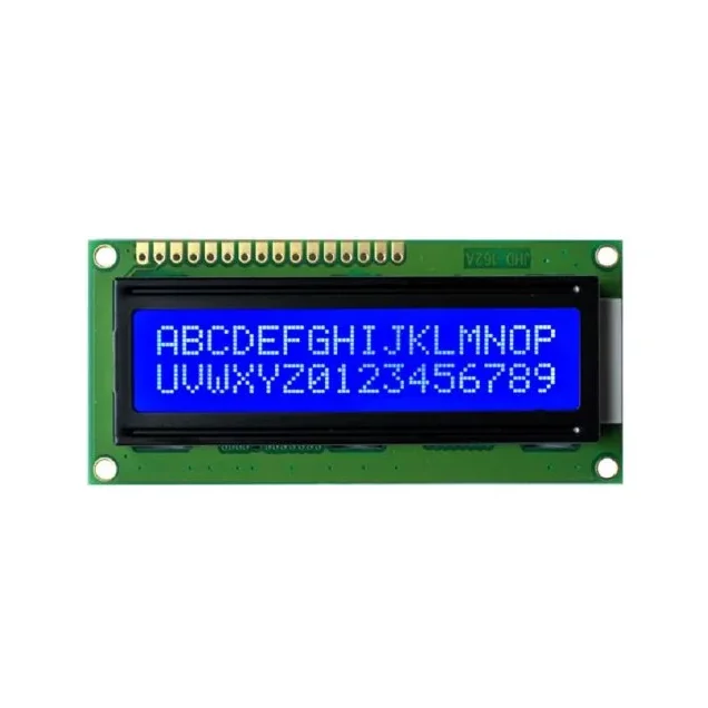
JHD 16×2 Character LCD Display With Blue Backlight
[LED/LCD Display Module] If you want to add some visual output to your Arduino projects, you’ll need a display. If you need only a little to display, the LCD 16×2 Parallel LCD Display is a quite good solution. This is a Original JHD 16×2 Character LCD Display With Blue Backlight as there are many fake JHD Displays in the Market. This is a great blue backlight LCD display. It is fantastic for Arduino based project. This LCD 16×2 Parallel LCD Display with Blue Backlight is very easy to interface with Arduino or Other Microcontrollers. This is LCD 16×2 Parallel LCD Display that provides a simple and cost-effective solution for adding a 16×2 White on RGB Liquid Crystal Display into your project. The display is 16 character by 2 line display that has a very clear and high contrast white text upon a blue background/backlight. The values shown on the display can be either simple text or numerical values read by the sensors, such as temperature or pressure, or even the number of cycles that the Arduino is performing. For more displays click below, LED/LCD Display Features : 16 characters wide, 2 rows White text on the yellow background Single LED backlight included can be dimmed easily with a resistor or PWM. Can be fully controlled with only 6 digital lines! (Any analog/digital pins can be used) Specifications: Model: JHD659 B/W Display: 16×2 character Outline: 80.0×36.0×14.5 VA: 64.5×14.5 Controller: SPLC780D Character: 2.95×4.35 Driver: 1/16 LCD: STN Blue Negative Backlight: White LED Package Includes : 1 x JHD 16×2 Character LCD Display With Blue Backlight
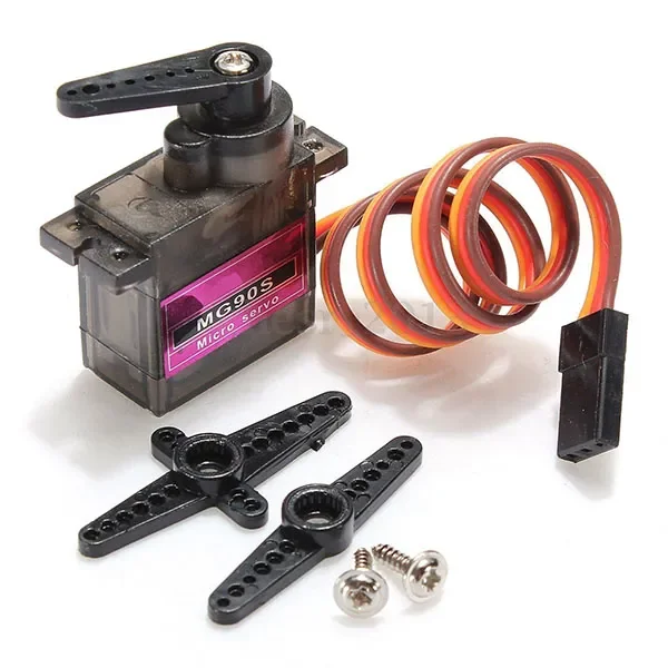
TowerPro Metal Gear MG90S Mini Digital Servo Motor (180° Rotation)
[Servo Motor] ⚙️ TowerPro MG90S Mini Digital Metal Gear Servo Motor (180°) Metal Gear • Digital Servo • 180° Rotation • High Precision • Ideal for RC & Robotics The TowerPro MG90S Mini Digital Servo Motor is a compact, high-performance 9g metal gear servo designed for precise position control in robotics, RC models, automation, and DIY electronics projects. Equipped with all-metal gears, a digital control circuit, and high positioning accuracy, the MG90S offers greater durability, faster response, and higher torque than standard plastic gear servos. Operating from 4.8V to 6.0V DC, the servo delivers a stall torque of up to 2.2 kg·cm and a rotation angle of approximately 180°, making it ideal for robotic arms, pan-tilt camera systems, RC airplanes, RC cars, boats, educational kits, and embedded control applications. The standard 3-wire JR/Futaba-compatible connector allows direct interfacing with Arduino, ESP32, Raspberry Pi, STM32, and most RC receivers. Its lightweight design, compact dimensions, and excellent holding torque make the MG90S one of the most popular micro servos for hobbyists, students, and professionals alike. ⭐ Features Genuine TowerPro MG90S digital servo Durable all-metal gear transmission Approximate 180° rotation angle High positioning accuracy Fast control response High holding torque Smooth and quiet operation Lightweight and compact design Standard 3-wire servo interface Compatible with Arduino, ESP32, Raspberry Pi and RC receivers Ideal for robotics, RC models and automation projects 📋 Technical Specifications Product Type: Mini Digital Servo Motor Brand: TowerPro Model: MG90S Gear Type: Metal Gear Rotation Angle: Approximately 180° Operating Voltage: 4.8V–6.0V DC Stall Torque: 1.8 kg·cm @ 4.8V 2.2 kg·cm @ 6.0V Operating Speed: 0.10 sec/60° @ 4.8V 0.08 sec/60° @ 6.0V Control Signal: PWM (50Hz Standard Servo Signal) Dead Band Width: 1µs Connector Type: JR / Futaba Compatible Cable Length: Approximately 25cm Dimensions: 22.8 × 12.2 × 28.5 mm Weight: Approximately 13.4g Operating Temperature: 0°C to +55°C These specifications are consistent with the manufacturer's published specifications. 🔧 Applications Suitable for: Arduino Projects ESP32 Projects Raspberry Pi Projects Robotic Arms Humanoid Robots RC Airplanes RC Cars RC Boats Pan-Tilt Camera Systems Automatic Door Mechanisms DIY Electronics Educational Robotics Smart Automation Projects Mechatronics Projects 📦 Package Includes 1 × TowerPro MG90S Mini Digital Servo Motor 1 × Servo Horn Set Single Arm Horn Double Arm Horn Four Arm Horn 1 × Mounting Screw Set ⚠️ Note Operate the servo only within the recommended 4.8V–6.0V DC supply range. For stable operation, use an external regulated power supply when driving the servo from microcontrollers. Product appearance, cable color, or accessories may vary slightly depending on the manufacturing batch. Counterfeit MG90S servos are common in the market. Purchase from trusted suppliers for genuine performance.
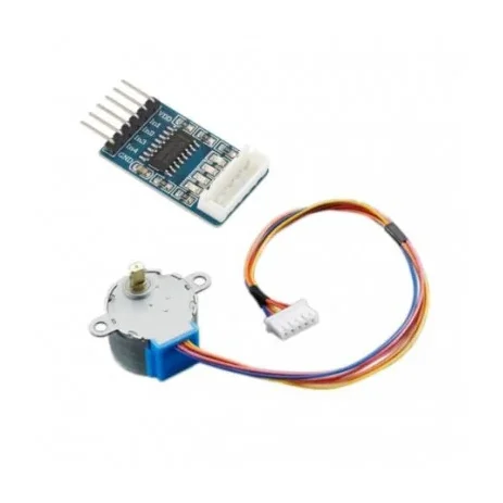
Stepper Motor(28YBJ-48) with SMD ULN2003 Driver Board
[Servo Motor] The 28BYJ-48 Stepper Motor with ULN2003 Driver Board is a compact, reliable, and low-cost 5V geared stepper motor kit designed for Arduino, robotics, automation, and embedded control applications. This motor features a 4-phase, 5-wire configuration with an integrated reduction gearbox, delivering high torque and precise positioning at low speeds. One of the biggest advantages of a stepper motor is its ability to operate accurately in an open-loop control system, eliminating the need for expensive feedback sensors or encoders. The motor position is precisely controlled by simply counting the input step pulses. The included ULN2003 driver board acts as a signal amplifier, allowing low-power control signals from microcontrollers such as Arduino, Raspberry Pi, ESP32, and 8051 to safely drive the stepper motor. The driver board also features four LED indicators (A, B, C, D) that display the working status of each phase in real time, making testing and debugging easy. With its compact size, plug-and-play connector, stable operation, and high reliability, this stepper motor kit is ideal for robot arms, CNC projects, camera sliders, 3D mechanisms, automation systems, and educational electronics projects. ⭐ KEY FEATURES ✔ 28BYJ-48 Mini Geared Stepper Motor – 5V DC✔ 4-Phase, 5-Wire Configuration✔ Includes ULN2003 Stepper Motor Driver Board✔ Open-Loop Precise Control – No encoder required✔ Built-in Gear Reduction for Higher Torque✔ Plug-and-Play Interface – Easy connection✔ Phase LED Indicators on driver board✔ Compact size, lightweight & reliable✔ Perfect for Arduino, robotics & automation projects 🔧 TECHNICAL SPECIFICATIONS Stepper Motor Model: 28BYJ-48 Supply Voltage: 5V DC (commonly used version) Number of Phases: 4 Wires: 5 Stride Angle: 5.625° × 1/64 (with gearbox) Gear Reduction Ratio: 1:64 (approx.) Dimensions: 44 × 44 × 28 mm (L × B × H) Type: Geared Stepper Motor Driver Board Driver Model: ULN2003 Input Interface: Standard 5-pin connector Indicators: 4 Phase LED status indicators Function: Signal amplification & motor driving 🎯 APPLICATIONS Arduino & microcontroller projects Robotics & automation systems Camera sliders & pan-tilt systems CNC & 3D motion mechanisms Educational electronics kits Smart home & IoT projects 📦 PACKAGE INCLUDES 1 × 28BYJ-48 5V Stepper Motor 1 × ULN2003 Stepper Motor Driver Board
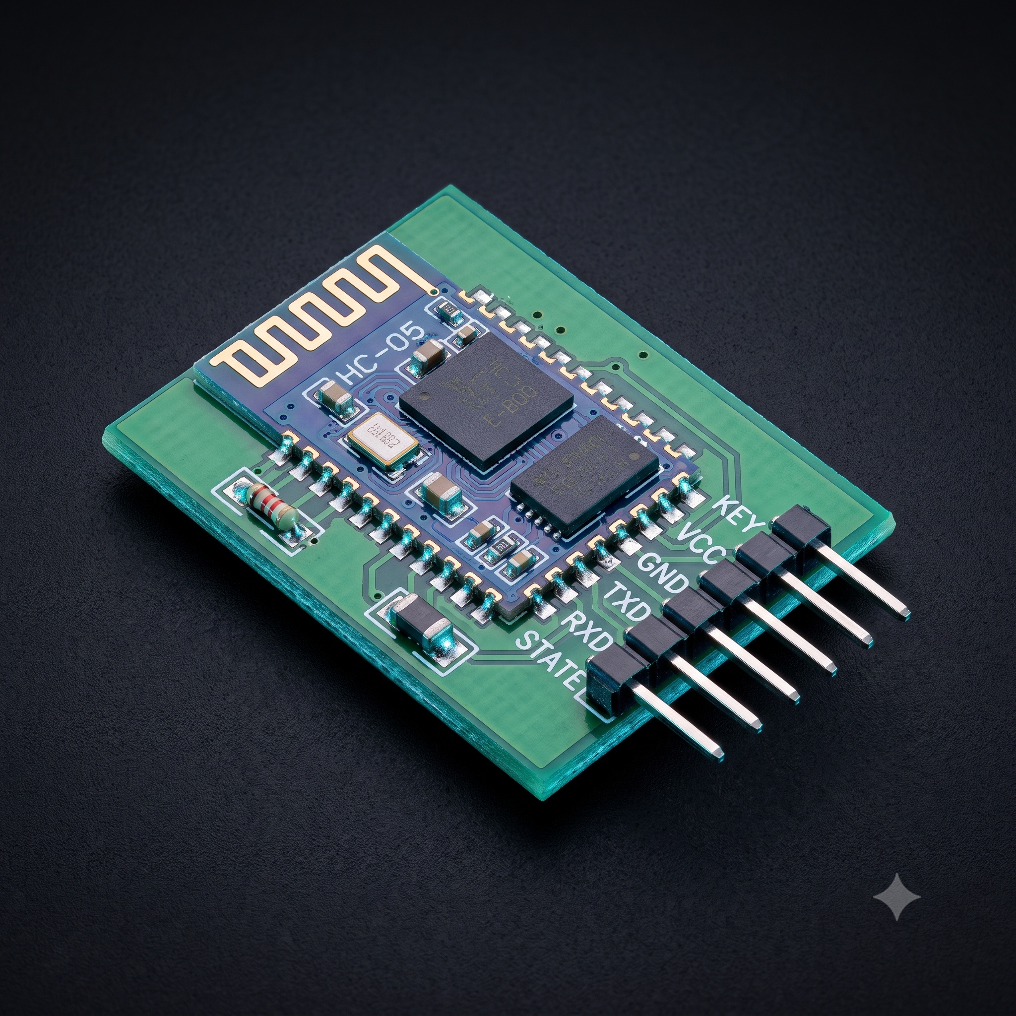
HC-05 6pin Bluetooth Module with Button
[Bluetooth Module] HC-05 Bluetooth Module Are you in search of an HC-05 Bluetooth Module, a versatile and cost-effective solution for your wireless communication needs? Look no further. This Bluetooth module offers seamless wireless communication for a wide range of applications, from GPS navigation systems to water and electricity meter readings. Whether you're an electronics enthusiast, a DIY hobbyist, or a professional looking for competitive pricing, this module is designed to meet your requirements. The HC-05 Bluetooth Module lets you switch between Master and Slave modes with ease using AT Commands, and it comes pre-configured in Slave Mode. Its compatibility with devices such as phones, laptops, and microcontrollers ensures hassle-free connectivity. With a USART interface, it's a perfect fit for microcontrollers supporting USART communication. Plus, you can configure its settings effortlessly using the command mode. Ideal for DIY projects and data exchange, this Bluetooth module provides LED feedback for seamless operation, giving you the best bang for your buck. Buy the HC-05 Bluetooth Module today and enjoy top-notch wireless communication at a competitive price. The HC-05 Bluetooth Module with Baseplate is a slave-only device. This means that it can connect to most phones and computers with Bluetooth but it cannot connect to another slave-only device such as keyboards and other HC-06 modules. To connect with other slave devices a master module would be necessary such as the HC-05 module ,which can do both master and slave. The slave mode in HC-05 Bluetooth cannot initiate a connection to another Bluetooth device but can accept connections. Master mode can initiate a connection to other devices. Key Features: Working current: matching for 30 mA, matching the communication for 8 mA. With the computer and Bluetooth adapter, PDA, seamless connection equipment. Use the CSR mainstream Bluetooth chip, Bluetooth V2.0 protocol standards. Potter default rate of 9600, the user can be set up. Bluetooth protocol: Bluetooth Specification v2.0+EDR Speed: Asynchronous: 2.1Mbps(Max) / 160 kbps, Synchronous: 1Mbps/1Mbps. Security: Authentication and encryption. Profiles: Bluetooth serial port. HC-05 Bluetooth Module Pin Diagram: HC-05 Bluetooth Module Pin Description: Pin Number Pin Name Description 1 Enable / Key This pin is used to switch between command mode (set low) and Data Mode (set high). The default setting of this HC 05 Bluetooth module is Data Mode. 2 Vcc This pin can be used to power the Bluetooth module. It has an operating voltage of +5V DC. 3 Ground Connect the module's ground pin to the Microcontroller’s Ground Pin (GND). 4 TX – Transmitter Sends serial data to the MCU. This pin will distribute all Bluetooth data in the form of serial data to the Microcontroller. 5 RX – Receiver Obtain Serial Data. This pin will transmit all serial data that is provided to it over Bluetooth. 6 State The on-board LED attached to the state pin can be used as feedback to see if Bluetooth is functioning properly. 7 LED Indicates the status of Module Blink once in 2 sec: Command Mode Repeated Blink: Waiting for connection in Data Mode Blink twice in 1 sec: Connection successful in Data Mode 8 Button Used to control the Key/Enable pin to switch between Data Mode and command Mode HC-05 Default Values: Bluetooth Name: “HC-05” Password: 1234 or 0000 Communication: Slave Mode: Data Mode Data Mode Baud Rate: 9600, 8, N, 1 Applications Can be used for wireless communication between two microcontroller units. Communicate with Laptop mobile phones etc. Data Logging Wireless Robots DIY Home Automation Projects GPS-based DIY projects. Specifications: Serial communications 9600-115200bps Frequency 2.4~2.524 GHz Power Supply 5VDC Operating Current 30mA Range <100m Dimensions 30mm x 14mm x 2.2 mm Weight 5 grams Package Includes: 1 x HC-05 Bluetooth Module
 Out of stock
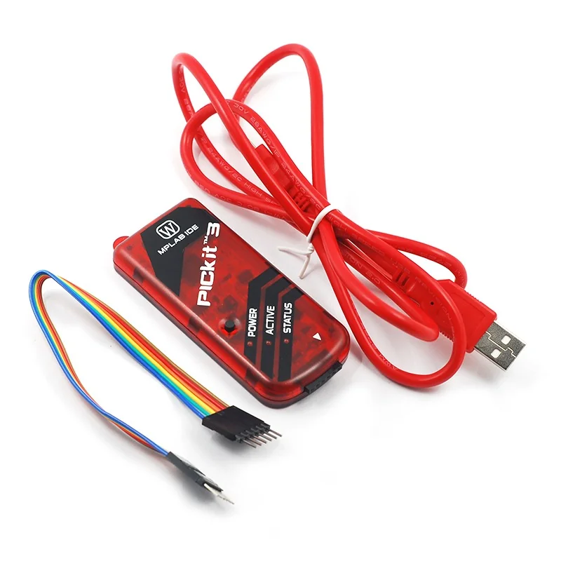
PICkit3 Debugger Programmer Emulator Controller Development Board
[Uncategorized] This is PICkit3 Debugger Programmer Emulator Controller Development board w/ Pinout diagram to ease the customer. The USB connection is more stable than ICD2. PICKIT3.5, begin to support Win7 system. Full patch design, patch through the reflow soldering processing, more stable quality. PIC developing data, C language development tool manual. A lot of PIC basic experiment program code; ICD2 PICKIT3 etc application specification. The MPLAB PICkit 3 allows debugging and programming of PIC® and dsPIC® Flash microcontrollers at a most affordable price point using the powerful graphical user interface of the MPLAB Integrated Development Environment (IDE). The MPLAB PICkit 3 is connected to the design engineer’s PC using a full-speed USB interface and can connect to the target via a Microchip debug (RJ-11) connector (compatible with MPLAB ICD 2, MPLAB ICD 3 and MPLAB REAL ICE). Pickit3 Pinout: Features : Full-speed USB support using Windows standard drivers Real-time execution Processors run at maximum speeds Built-in over-voltage/short circuit monitor Low voltage to 5V (1.8 to the 5V range) Read/write program and data memory of the microcontroller Diagnostic LEDs (power, active, status) Read/write program and data memory of the microcontroller 1Erase of all memory types (EEPROM, ID, configuration, and program) with verification Peripheral freeze at the breakpoint. Program up to 512K byte flash. Package Includes : 1 x PICKIT3 Programmer. 1 x USB cable 1x 6pin cable A DVD
 Out of stock
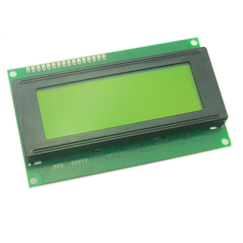
LCD2004 Parallel LCD Display Yellow Backlight with IIC/I2C Interface
[LED/LCD Display Module] If you want to add some visual output to your Arduino projects, you’ll need a display. If you need moderate data on display, the LCD2004 Parallel LCD Display is a quite good solution. This is LCD2004 Parallel LCD Display that provides a simple and cost-effective solution for adding a 20×4 Black on RGB Liquid Crystal Display into your project. The display is 20 character by 4 line display has a very clear and high contrast black text upon a yellow background/backlight. This is great yellow backlight LCD display. It is fantastic for Arduino based project. This LCD2004 Parallel LCD Display with Yellow Backlight is very easy to interface with Arduino or Other Microcontrollers. The values shown on the display can be either a simple text or numerical values read by the sensors, such as temperature or pressure, or even the number of cycles that the Arduino is performing. One thing to consider is you’ll waste about 8 Pins on your Arduino for the display to get working. Luckily there exists an I2C adapter that you can solder right onto the pins of the display. So all you need to connect are the I2C pins, which shows a good library and little of coding. For more displays click below, LED/LCD Display Features : 20 characters wide, 4 rows Black text on the yellow background The module can easily interface with an MCU The module is a low-power consumption character LCD Module with a built-in controller Single LED backlight included can be dimmed easily with a resistor or PWM. Can be fully controlled with only 6 digital lines! (Any analog/digital pins can be used) Package Includes : 1 x LCD2004 Parallel LCD Display Yellow Backlight with IIC/I2C Interface
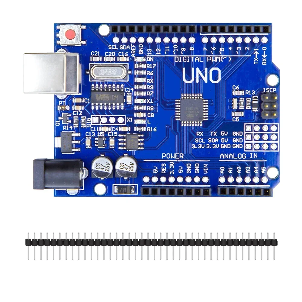
Arduino Uno R3 CH340G ATMega328P Development Board Compatible with Arduino
[Arduino Boards, Development Board] Product Description The Uno R3 CH340G ATmega328p Development Board is the low-cost version of the popular Uno R3 Arduino. It is assembled with the CH340 USB to Serial converter chip, instead of using an Atmega16U2 chip. We have used plenty of these low-cost Arduino boards with CH340 chips, and have found them to work perfectly. The only time the CH340 chip is used is during programming and when using the serial output of the USB port. During normal operation, this board is identical to the more expensive version without CH340 chip. Features The Arduino Uno R3 is a micro-controller board base on the ATmega328 . It has 14 digital input/output pins (of which 6 can be used as PWM outputs); 6 analog inputs, a 16 MHz ceramic resonator, a USB connection, a power jack, an ICSP header, and a reset button. It contains everything need to support the micro-controller; simply connect it to a computer with a USB cable or power it with a AC-to-DC adapter or battery to get start. The Arduino Uno R3 differs from all preceding boards in that it does not use the FTDI USB-to-serial driver chip. Instead, it features the Atmega16U2 (Atmega8U2 up to version R2) program as a USB-to-serial converter. Revision 2 of the Uno board has a resistor pulling the 8U2 HWB line to ground, making it easier to put into DFU mode. Note: The Arduino Uno R3 reference design can use an Atmega8, 168, or 328, Current models use an ATmega328, but an Atmega8 is shown in the schematic for reference. The pin configuration is identical on all three processors. Package Includes 1 x Arduino Uno R3 CH340G ATMega328P Development Board
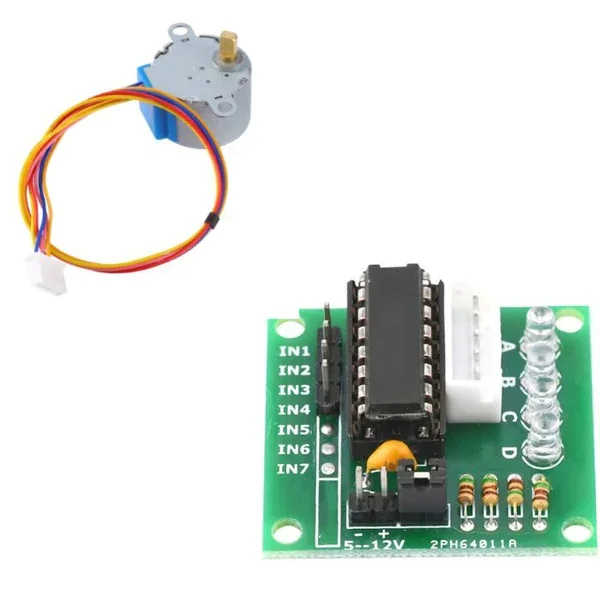
Stepper Motor(28YBJ-48) with ULN2003 Driver Board
[Servo Motor] The 28BYJ-48 Stepper Motor with ULN2003 Driver Board is a compact, reliable, and low-cost 5V geared stepper motor kit designed for Arduino, robotics, automation, and embedded control applications. This motor features a 4-phase, 5-wire configuration with an integrated reduction gearbox, delivering high torque and precise positioning at low speeds. One of the biggest advantages of a stepper motor is its ability to operate accurately in an open-loop control system, eliminating the need for expensive feedback sensors or encoders. The motor position is precisely controlled by simply counting the input step pulses. The included ULN2003 driver board acts as a signal amplifier, allowing low-power control signals from microcontrollers such as Arduino, Raspberry Pi, ESP32, and 8051 to safely drive the stepper motor. The driver board also features four LED indicators (A, B, C, D) that display the working status of each phase in real time, making testing and debugging easy. With its compact size, plug-and-play connector, stable operation, and high reliability, this stepper motor kit is ideal for robot arms, CNC projects, camera sliders, 3D mechanisms, automation systems, and educational electronics projects. ⭐ KEY FEATURES ✔ 28BYJ-48 Mini Geared Stepper Motor – 5V DC✔ 4-Phase, 5-Wire Configuration✔ Includes ULN2003 Stepper Motor Driver Board✔ Open-Loop Precise Control – No encoder required✔ Built-in Gear Reduction for Higher Torque✔ Plug-and-Play Interface – Easy connection✔ Phase LED Indicators on driver board✔ Compact size, lightweight & reliable✔ Perfect for Arduino, robotics & automation projects 🔧 TECHNICAL SPECIFICATIONS Stepper Motor Model: 28BYJ-48 Supply Voltage: 5V DC (commonly used version) Number of Phases: 4 Wires: 5 Stride Angle: 5.625° × 1/64 (with gearbox) Gear Reduction Ratio: 1:64 (approx.) Dimensions: 44 × 44 × 28 mm (L × B × H) Type: Geared Stepper Motor Driver Board Driver Model: ULN2003 Input Interface: Standard 5-pin connector Indicators: 4 Phase LED status indicators Function: Signal amplification & motor driving 🎯 APPLICATIONS Arduino & microcontroller projects Robotics & automation systems Camera sliders & pan-tilt systems CNC & 3D motion mechanisms Educational electronics kits Smart home & IoT projects 📦 PACKAGE INCLUDES 1 × 28BYJ-48 5V Stepper Motor 1 × ULN2003 Stepper Motor Driver Board
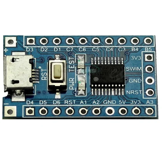
Core Board STM8S103F3P6 STM8 Development Board Minimum System Board
[Development Board] Connection Diagram: Features : Chipboard STM32F103C8T6 On board, SWIM interface and reset button Micro USB line or the 2.54 pin to link to the power with the input voltage 4.5V-15V. Power light and the Demo indicator light Leads all the pins and has detailed label for the Pins. Support SWIM debug mode. Package Includes : 1 x Core Board STM8S103F3P6 STM8 Development Board
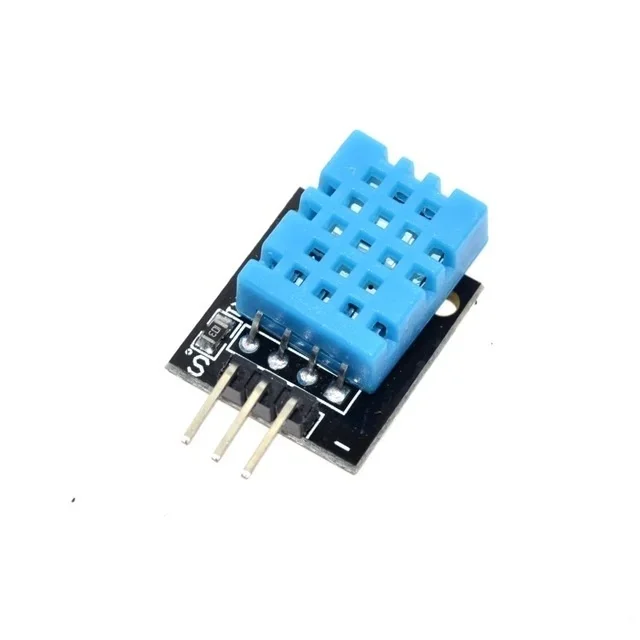 Out of stock
DHT11 Temperature and Humidity Sensor Module Digital Output 3.3V-5V
[Temperature Sensor] The DHT11 Temperature and Humidity Sensor Module is a compact and reliable environmental sensing module designed to measure surrounding temperature and humidity levels. Based on the popular DHT11 sensor, it combines a humidity sensing component and a temperature sensor with a calibrated digital signal output. In addition, the module provides direct digital data output, eliminating the need for complex analog signal processing. As a result, it can be easily interfaced with Arduino, ESP32, Raspberry Pi, STM32, and other microcontroller platforms. Because of its low power consumption and stable performance, the DHT11 sensor is widely used in weather monitoring systems, home automation, greenhouse monitoring, HVAC systems, and educational electronics projects. Furthermore, the onboard mounting holes allow quick and secure installation. The module operates from 3.3V to 5V DC, making it suitable for both 3.3V and 5V microcontroller systems. Moreover, it offers good long-term stability and reliable environmental monitoring performance. 🔹 Key Features Based on DHT11 temperature and humidity sensor Digital signal output Low power consumption High reliability and long-term stability Measures temperature and humidity simultaneously Compatible with 3.3V and 5V systems Easy interfacing with microcontrollers Compact PCB module design Onboard power indicator LED Mounting holes for easy installation 🔹 Technical Specifications Sensor Type: DHT11 Operating Voltage: 3.3V – 5V DC Output Signal: Digital Output Humidity Measurement Range: 20%RH – 95%RH Humidity Accuracy: ±5%RH Temperature Measurement Range: 0°C to 50°C Temperature Accuracy: ±2°C Sampling Rate: 1Hz (One Reading Per Second) Power Indicator: Red LED Mounting Type: PCB Module with Fixing Holes Interface: 3-Pin Digital Interface 🔹 Pin Configuration VCC – Power Supply (3.3V–5V) DATA – Digital Signal Output GND – Ground 🔹 Applications This sensor module is suitable for: Arduino projects ESP32 projects Raspberry Pi projects Weather stations Greenhouse monitoring Home automation systems HVAC monitoring IoT applications Environmental monitoring systems Educational electronics projects 🔹 Package Includes 1 × DHT11 Temperature and Humidity Sensor Module