
All products · 6 of 1440
Electronics, sensors, robotics kits, PC components, peripherals — everything Unik Systems carries, in one place.
Stepper Motor 28BYJ-48 + ULN2003 Driver
28BYJ-48 ULN2003 5V stepper motor + ULN2003 driver board.
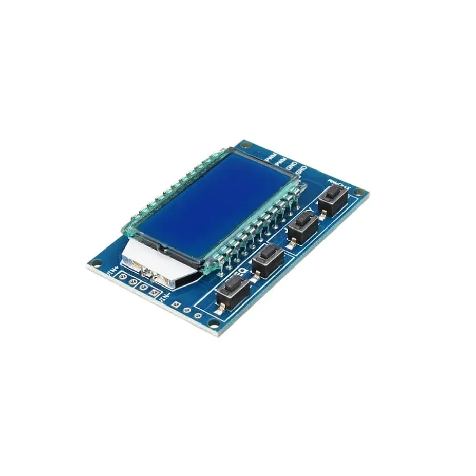
XY-LPWM Signal Generator PWM Pulse Frequency Duty Cycle Adjustable Module LCD Display Module
XY-LPWM Signal Generator PWM Pulse Frequency Duty Cycle Adjustable Module LCD Display Module is a two-channel PWM signal generator. It has dedicated switches for adjusting the frequency and duty cycle separately. Using this module PWM output, frequency and duty cycle can be set as per requirements. Communication Standard: 9600 bps Data bits: 8 Stop bit: 1 Check digit: none Flow control: none Set the frequency of the PWM “F101”: Set the frequency to 101 Hz (001 to 999) “F1.05”: set the frequency of 1.05 kHz (1.00 ~ 9.99) “F10.5”: Set the frequency to 10.5kHz (10.0 ~ 99.9) “F1.0.5”: set the frequency of 105kHz (1.0.0 ~ 1.5.0) Set the PWM duty cycle “DXXX”: set the PWM duty cycle to XXX; (001 ~ 100) Such as D050, set the PWM duty cycle is 50% Read the set parameters Send a “read” string to read the set parameters. Set successfully return: DOWN; Setup failed to return: FALL. Application: This is used to drive a stepper motor driver’s square wave. Generate an adjustable pulse for MCU. Generate an adjustable pulse for controlling relative circuit (PWM adjust lightspeed, etc). Used as a square wave signal generator for experimental development and use. Parameter Settings: The module has 4 switches, two for frequency adjustment and two for duty cycle adjustment. This module can generate frequencies between 1Hz and 150kHz, with automatic switching for different ranges. Frequency is divided into four ranges, automatic switching: 1. XXX (no decimal point): the smallest unit is 1Hz, the value range of 1Hz ~ 999Hz; 2. X.XX (decimal point in the hundred) the smallest unit is 0.01Khz, the range of 1.00Khz ~ 9.99Khz; 3. XX.X (decimal point in ten): the smallest unit is 0.1Khz; value range of 10.0KHz ~ 99.9KHz 4. X.X.X (decimal point in ten and hundred): the smallest unit is 1Khz; value range 1KHz ~ 150KHz 5. e.g. frequency display: 100 indicates PWM output 100Hz pulse; 1.01 indicates PWM output 1.01K pulse; 54.1 indicates that the PWM output has a pulse of 54.1 kHz; 1.2.4 indicates that the PWM output is 124 kHz pulse; Duty cycle range: 1 – 100%. In case of a power outage or if the module is powered down, the parameters that are set are saved automatically, so there is no need to set the parameters again. Single touch for increasing or decreasing single unit and long press for fast increasing or decreasing. Features: LCD display for frequency and duty cycle. Wide frequency range. High precision. Serial communication(TTL based). Package Includes: 1 x XY-LPWM Signal Generator PWM Pulse Frequency Duty Cycle Adjustable Module LCD Display Module.
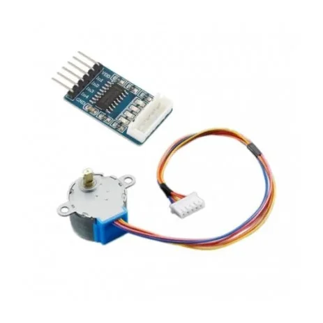
Stepper Motor(28YBJ-48) with SMD ULN2003 Driver Board
[Servo Motor] The 28BYJ-48 Stepper Motor with ULN2003 Driver Board is a compact, reliable, and low-cost 5V geared stepper motor kit designed for Arduino, robotics, automation, and embedded control applications. This motor features a 4-phase, 5-wire configuration with an integrated reduction gearbox, delivering high torque and precise positioning at low speeds. One of the biggest advantages of a stepper motor is its ability to operate accurately in an open-loop control system, eliminating the need for expensive feedback sensors or encoders. The motor position is precisely controlled by simply counting the input step pulses. The included ULN2003 driver board acts as a signal amplifier, allowing low-power control signals from microcontrollers such as Arduino, Raspberry Pi, ESP32, and 8051 to safely drive the stepper motor. The driver board also features four LED indicators (A, B, C, D) that display the working status of each phase in real time, making testing and debugging easy. With its compact size, plug-and-play connector, stable operation, and high reliability, this stepper motor kit is ideal for robot arms, CNC projects, camera sliders, 3D mechanisms, automation systems, and educational electronics projects. ⭐ KEY FEATURES ✔ 28BYJ-48 Mini Geared Stepper Motor – 5V DC✔ 4-Phase, 5-Wire Configuration✔ Includes ULN2003 Stepper Motor Driver Board✔ Open-Loop Precise Control – No encoder required✔ Built-in Gear Reduction for Higher Torque✔ Plug-and-Play Interface – Easy connection✔ Phase LED Indicators on driver board✔ Compact size, lightweight & reliable✔ Perfect for Arduino, robotics & automation projects 🔧 TECHNICAL SPECIFICATIONS Stepper Motor Model: 28BYJ-48 Supply Voltage: 5V DC (commonly used version) Number of Phases: 4 Wires: 5 Stride Angle: 5.625° × 1/64 (with gearbox) Gear Reduction Ratio: 1:64 (approx.) Dimensions: 44 × 44 × 28 mm (L × B × H) Type: Geared Stepper Motor Driver Board Driver Model: ULN2003 Input Interface: Standard 5-pin connector Indicators: 4 Phase LED status indicators Function: Signal amplification & motor driving 🎯 APPLICATIONS Arduino & microcontroller projects Robotics & automation systems Camera sliders & pan-tilt systems CNC & 3D motion mechanisms Educational electronics kits Smart home & IoT projects 📦 PACKAGE INCLUDES 1 × 28BYJ-48 5V Stepper Motor 1 × ULN2003 Stepper Motor Driver Board
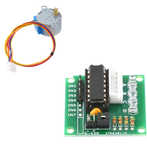
Stepper Motor(28YBJ-48) with ULN2003 Driver Board
[Servo Motor] The 28BYJ-48 Stepper Motor with ULN2003 Driver Board is a compact, reliable, and low-cost 5V geared stepper motor kit designed for Arduino, robotics, automation, and embedded control applications. This motor features a 4-phase, 5-wire configuration with an integrated reduction gearbox, delivering high torque and precise positioning at low speeds. One of the biggest advantages of a stepper motor is its ability to operate accurately in an open-loop control system, eliminating the need for expensive feedback sensors or encoders. The motor position is precisely controlled by simply counting the input step pulses. The included ULN2003 driver board acts as a signal amplifier, allowing low-power control signals from microcontrollers such as Arduino, Raspberry Pi, ESP32, and 8051 to safely drive the stepper motor. The driver board also features four LED indicators (A, B, C, D) that display the working status of each phase in real time, making testing and debugging easy. With its compact size, plug-and-play connector, stable operation, and high reliability, this stepper motor kit is ideal for robot arms, CNC projects, camera sliders, 3D mechanisms, automation systems, and educational electronics projects. ⭐ KEY FEATURES ✔ 28BYJ-48 Mini Geared Stepper Motor – 5V DC✔ 4-Phase, 5-Wire Configuration✔ Includes ULN2003 Stepper Motor Driver Board✔ Open-Loop Precise Control – No encoder required✔ Built-in Gear Reduction for Higher Torque✔ Plug-and-Play Interface – Easy connection✔ Phase LED Indicators on driver board✔ Compact size, lightweight & reliable✔ Perfect for Arduino, robotics & automation projects 🔧 TECHNICAL SPECIFICATIONS Stepper Motor Model: 28BYJ-48 Supply Voltage: 5V DC (commonly used version) Number of Phases: 4 Wires: 5 Stride Angle: 5.625° × 1/64 (with gearbox) Gear Reduction Ratio: 1:64 (approx.) Dimensions: 44 × 44 × 28 mm (L × B × H) Type: Geared Stepper Motor Driver Board Driver Model: ULN2003 Input Interface: Standard 5-pin connector Indicators: 4 Phase LED status indicators Function: Signal amplification & motor driving 🎯 APPLICATIONS Arduino & microcontroller projects Robotics & automation systems Camera sliders & pan-tilt systems CNC & 3D motion mechanisms Educational electronics kits Smart home & IoT projects 📦 PACKAGE INCLUDES 1 × 28BYJ-48 5V Stepper Motor 1 × ULN2003 Stepper Motor Driver Board
 Out of stock
L293D Stepper Motor Driver IC Chip
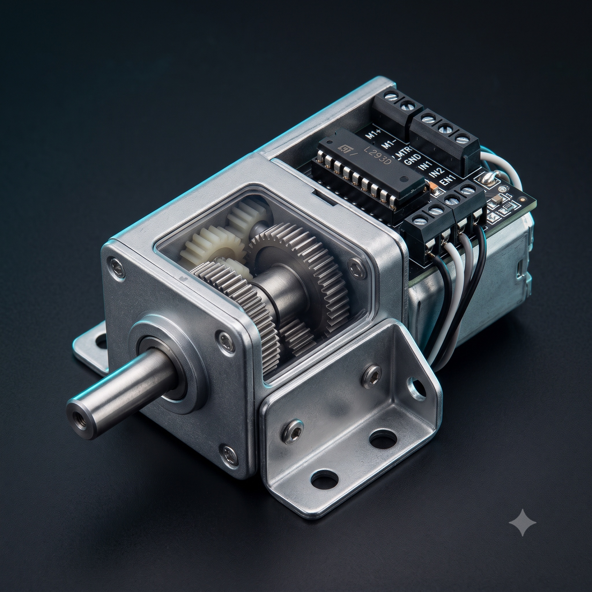
[Semiconductor ICs] L293D Stepper Motor Driver IC is a dual H-bridge motor driver integrated circuit (IC). Motor drivers act as current amplifiers since they take a low-current control signal and provide a higher-current signal. This higher current signal is used to drive the motors. Features: Featuring Unit rode L293 and L293D Wide Supply-Voltage Range: 4.5 V to 36 V Separate Input-Logic Supply Internal ESD Protection Thermal Shutdown High-Noise-Immunity Inputs Output Current 1 A Per Channel (600 mA for L293D) Peak Output Current 2 A Per Channel (1.2 A for L293D) Output Clamp Diodes for Inductive Transient Suppression (L293D) Applications: High Current Motor Driver IC. Dual H-bridge for controlling up to two motors at a time. Ideal for Inductive load decoupling from the main/control unit. A wide voltage range allows for an adaptive voltage range control. Package Includes: 1 x L293D Driver IC
 Out of stock
A4988 driver Stepper Motor Driver- Good Quality
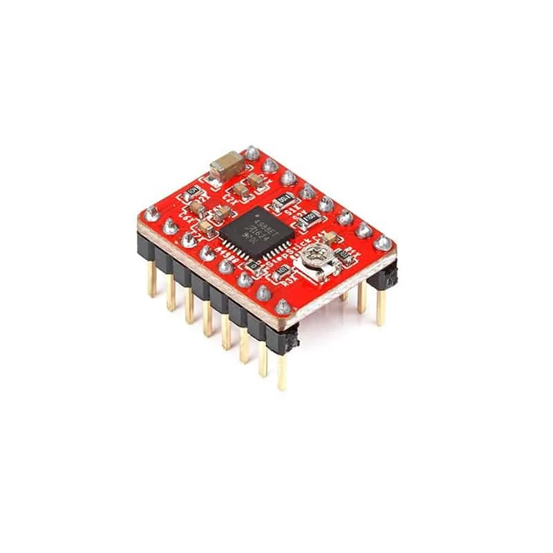
[Brushed DC motor Driver] Features : Automatic current decay mode detection/choice. Mixed with slow current decay mode. The low power dissipation of synchronous rectifier. Internal UVLO(ultra voltage lockout). Crossover current protection. Thermal shutdown circuit. Ground fault protection. Loading and short circuit protection. The optional five-step mode: full, 1/2, 1/4, 1/8 and 1/16. Package Includes : 1 x A4988 Stepper Motor Driver- Normal quality. 1 x Heat sink.