
All products · 31 of 1440
Electronics, sensors, robotics kits, PC components, peripherals — everything Unik Systems carries, in one place.

IOT Plug & Play
MCU: ESP8266/ESP32 based (Wi-Fi 2.4GHz). Supply: 5V input, onboard 3.3V regulation. Protocols: MQTT/HTTP. Cloud/App support. GPIO with pre-wired ports. Typical sensors: DHT11/22, LDR, relay module, IR, PIR.
 Only 1 left
IOT Smarthome Kit
MCU: ESP8266/ESP32. Modules: 1–4 channel relay (optocoupled preferred), PIR, LDR, DHT. Control: app/web dashboard. Protocols: MQTT/HTTP. Power: 5V input. Properly isolated AC relay use.
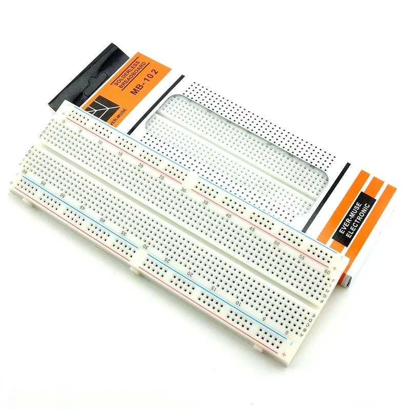
Breadboard Kit
Breadboard: 400/830 tie-points. Jumpers: M-M, M-F. Common parts: resistors (¼W), LEDs, push buttons, potentiometer. Modules: LDR, buzzer, IR, PIR, relay. Power module: 3.3V/5V rails (optional).
 Only 1 left
Play Mex
MCU: ESP8266/ESP32. Sensors: soil moisture (capacitive preferred), temp/humidity (DHT), light sensor. Actuation: relay/pump/solenoid valve demo. Dashboard: MQTT/HTTP. Power: 5V input + relay isolation.
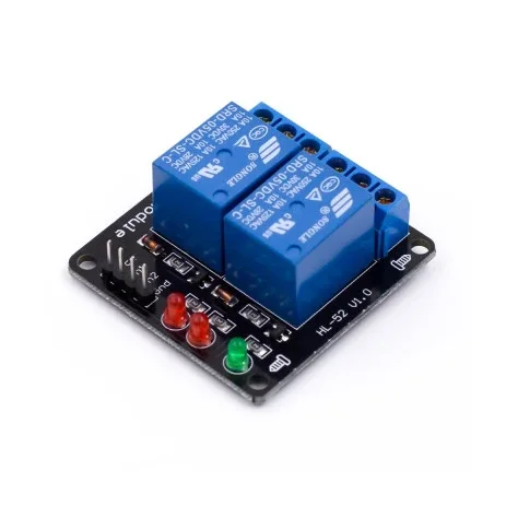
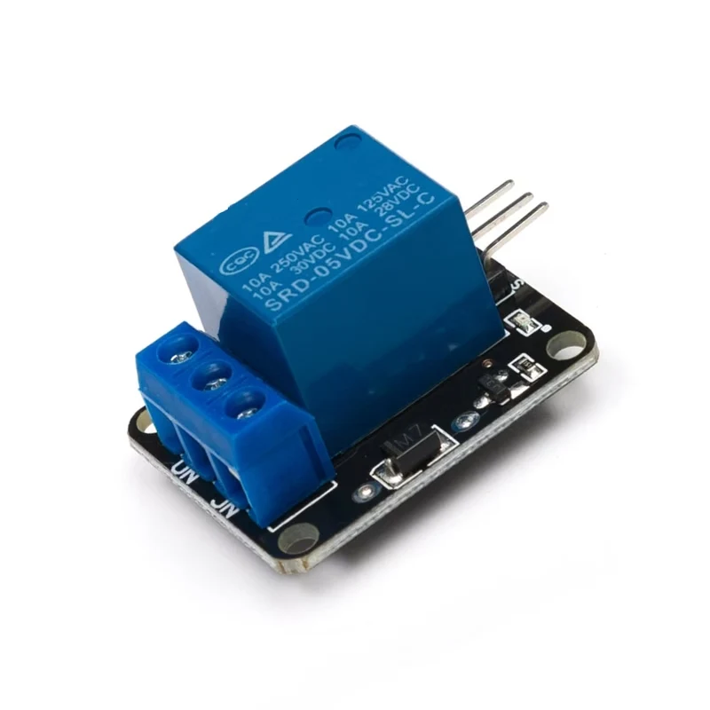
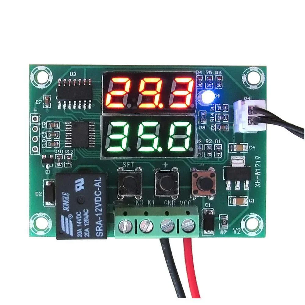
XH-W1219 12V Digital Temperature Controller Module with Dual LED Display & Waterproof NTC Sensor
[Relay Module, Temperature Sensor] 🌡️ XH-W1219 12V Digital Temperature Controller Module with Dual LED Display & Waterproof NTC Sensor Dual LED Display • 12V DC Operation • 10A Relay Output • Heating & Cooling Modes • Waterproof NTC Sensor The XH-W1219 12V Digital Temperature Controller Module is a high-precision thermostat controller designed for automatic temperature monitoring and control in heating and cooling applications. Powered by 12V DC, this module features a dual LED display that simultaneously shows the current temperature and set temperature, making operation more convenient than the popular W1209 controller. Equipped with a waterproof NTC 10K temperature sensor, the XH-W1219 accurately measures temperatures from -50°C to +110°C. The onboard 10A relay output can directly control heaters, cooling fans, pumps, compressors, and other electrical loads within its rated capacity. The module is based on a Nuvoton microcontroller, which stores all settings in non-volatile memory, ensuring that user configurations are retained even after power loss. It supports both Heating (H) and Cooling (C) modes, adjustable hysteresis, temperature calibration, delay start, and high-temperature alarm functions. Ideal for incubators, aquariums, refrigeration systems, greenhouse automation, HVAC equipment, battery temperature monitoring, and industrial automation, the XH-W1219 provides reliable and accurate temperature control in a compact module. ⭐ Features Dual LED display for simultaneous temperature and setpoint display Operates on 12V DC High-accuracy waterproof NTC 10K temperature sensor Temperature control range from -50°C to +110°C Supports Heating and Cooling modes Built-in 10A relay output Adjustable temperature hysteresis Temperature calibration function Adjustable relay delay start High-temperature alarm function Stores settings in non-volatile memory Easy configuration using three push buttons High measurement accuracy (0.1°C resolution) Based on a Nuvoton MCU Compact PCB design with mounting holes 📋 Technical Specifications Product Type: Digital Temperature Controller Module Model: XH-W1219 Operating Voltage: 12V DC Display: Dual 3-Digit LED (Current Temperature & Set Temperature) Temperature Sensor: Waterproof NTC 10K Thermistor Temperature Control Range: -50°C to +110°C Temperature Resolution: 0.1°C Temperature Calibration: -10°C to +10°C Relay Output: 10A (Maximum) Relay Contact Rating: Up to 120VAC 10A / 14VDC 10A Control Modes: Heating (H) / Cooling (C) Hysteresis Setting: 0.1°C to 30°C Delay Start: 0–10 Minutes High Temperature Alarm: -49°C to +110°C Memory: Non-Volatile Parameter Storage Controller: Nuvoton MCU Dimensions: Approx. 60 × 44 × 17 mm Weight: Approx. 22 g (may vary slightly by manufacturer) ⚙️ Parameter Functions Parameter Description P0 Heating (H) / Cooling (C) Mode Selection P1 Temperature Hysteresis (Return Difference) P2 Maximum Temperature Limit P3 Minimum Temperature Limit P4 Temperature Calibration P5 Relay Delay Start (0–10 Minutes) P6 High Temperature Alarm Setting 🔧 Applications Suitable for: Egg Incubators Aquarium Temperature Control Greenhouse Automation Refrigeration Systems Cooling Fans Heating Elements Water Heaters HVAC Systems Fermentation Equipment Battery Temperature Monitoring Industrial Automation Laboratory Equipment DIY Electronics Smart Home Projects Arduino & Raspberry Pi Projects (Relay Interface) 📦 Package Includes 1 × XH-W1219 12V Digital Temperature Controller Module 1 × Waterproof NTC 10K Temperature Sensor ⚠️ Note Operates only on 12V DC. The relay output is rated for 10A maximum. For higher-power loads, use an external contactor or relay. Sensor cable can be extended if required using appropriate wiring. Product appearance or PCB color may vary slightly depending on the manufacturing batch.
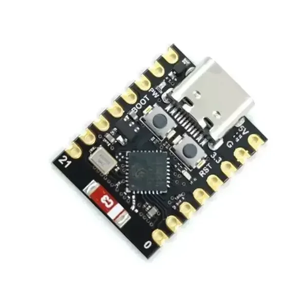
ESP32-C3 Super Mini Development Board With Headers Pins
[ESP Modules] Ultra Compact • Wi-Fi & BLE 5.0 • USB Type-C • Perfect for IoT & Embedded Projects The ESP32-C3 Super Mini Development Board is a compact, feature-rich development board built around the powerful ESP32-C3 SoC from Espressif. Powered by a 32-bit RISC-V single-core processor running at up to 160MHz, it combines 2.4GHz Wi-Fi, Bluetooth 5.0 Low Energy (BLE), and low-power operation in an ultra-small form factor. Designed for IoT, smart home, wireless communication, automation, and embedded system development, the ESP32-C3 Super Mini offers 4MB Flash memory, 400KB SRAM, multiple GPIOs, ADC, PWM, UART, SPI, and I2C interfaces for connecting sensors, displays, relays, and other peripherals. The onboard USB Type-C interface simplifies programming and power supply, while the built-in USB-to-Serial functionality enables quick firmware uploading without requiring additional programmers. Fully compatible with Arduino IDE, ESP-IDF, PlatformIO, and MicroPython, it is suitable for beginners, students, makers, and professional developers. Its ultra-compact breadboard-friendly design makes it ideal for portable and space-constrained projects where performance, wireless connectivity, and energy efficiency are essential. Note: Programming, software configuration, driver installation, firmware flashing, and coding-related issues are not covered under return or replacement. Users are expected to troubleshoot software-related issues independently. ⭐ Features Powerful ESP32-C3 32-bit RISC-V processor CPU frequency up to 160MHz Built-in 2.4GHz Wi-Fi (802.11 b/g/n) Integrated Bluetooth 5.0 Low Energy (BLE) Ultra-compact Super Mini design Breadboard-friendly layout USB Type-C interface for programming and power 4MB onboard Flash memory 400KB SRAM Multiple GPIO, ADC, PWM, UART, SPI & I2C interfaces Low power consumption with Deep Sleep mode Onboard programmable LED Compatible with Arduino IDE, ESP-IDF, PlatformIO & MicroPython Ideal for IoT, automation, robotics, and wireless applications 📋 Technical Specifications Product Type: Development Board Board Model: ESP32-C3 Super Mini Microcontroller: ESP32-C3 Processor Architecture: 32-bit RISC-V CPU Frequency: Up to 160MHz Core: Single Core Flash Memory: 4MB SRAM: 400KB Wi-Fi Standard: IEEE 802.11 b/g/n (2.4GHz) Bluetooth: Bluetooth 5.0 Low Energy (BLE) Operating Voltage: 3.3V Input Voltage: 5V via USB Type-C or 3.3V External USB Interface: USB Type-C GPIO: Multiple Digital GPIO Pins Analog Input: Up to 6 ADC Channels PWM: Supported UART: Supported SPI: Supported I2C: Supported USB-to-Serial: Onboard Onboard LED: User Programmable (GPIO8) Power Consumption: Ultra Low (Deep Sleep ≈ 43µA) Dimensions: Approx. 22.5 × 18 mm Headers: Pre-Soldered 🔧 Applications Suitable for: Internet of Things (IoT) Smart Home Automation Wireless Sensor Networks Home Automation Systems Bluetooth Low Energy Devices Wi-Fi Enabled Controllers Robotics Projects Data Logging Systems Remote Monitoring Industrial Automation Portable Embedded Devices Educational Learning DIY Electronics Projects Wearable Electronics Rapid Prototyping 📦 Package Includes 1 × ESP32-C3 Super Mini Development Board Pin Headers ⚠️ Note Programming, firmware installation, software configuration, and driver-related issues are not covered under warranty, return, or replacement. Please verify board compatibility and install the appropriate development environment before programming. Soldered and non-soldered header pin depend on stock
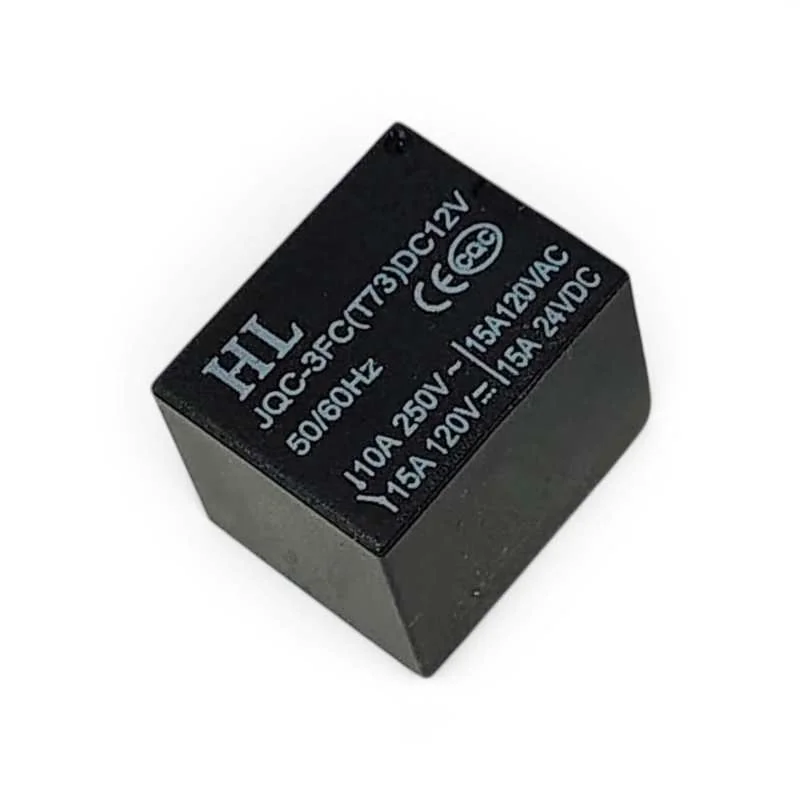
5 Pin Mini SPDT Relay 12V 10A 250V PCB Mount Electromagnetic Relay
[Relay Module, Relays] 12V PCB Mount Sugar Cube SPDT Relay – 5 Pin 10A The 12V PCB Mount Sugar Cube SPDT Relay is a compact Single Pole Double Throw (SPDT) electromagnetic relay designed for switching AC and DC electrical loads using a microcontroller, sensor, automation circuit, or other low-power control system. Its compact PCB-mount design makes it suitable for DIY electronics, home automation, security systems, switching circuits, motor control, lighting control, and embedded applications. The relay features a 12V DC coil and a 5-pin SPDT configuration consisting of two coil terminals, COM (Common), NO (Normally Open), and NC (Normally Closed) contacts. When the coil is energized, the internal contact switches between the NC and NO terminals. With contact ratings of up to 10A at 250V AC, 10A at 125V AC, 12A at 120V DC, and 10A at 28V DC, this relay is suitable for a wide range of electrical switching applications. ⭐ Key Features SPDT (Single Pole Double Throw) relay 12V DC coil Compact Sugar Cube design 5-pin configuration PCB mounting type 10A @ 250V AC contact rating 10A @ 125V AC contact rating 12A @ 120V DC contact rating 10A @ 28V DC contact rating Coil resistance: approximately 270Ω Approximately 45mA nominal coil current 50/60Hz frequency specification Fast switching response Suitable for microcontroller and sensor-controlled switching Ideal for automation and control applications 📋 Technical Specifications Product Type: PCB Mount Relay Relay Type: SPDT (Single Pole Double Throw) Contact Configuration: 1 Form C Number of Pins: 5 Coil Voltage: 12V DC Trigger Voltage: 12V DC Coil Resistance: 270Ω Nominal Coil Current: Approximately 45mA Frequency: 50/60Hz Maximum AC Load: 10A @ 250V AC Maximum AC Load: 10A @ 125V AC Maximum DC Load: 12A @ 120V DC Maximum DC Load: 10A @ 28V DC Operating Time: 10ms Release Time: 5ms Mounting Type: PCB Mount Contact Terminals: COM / NO / NC Coil Terminals: Coil End 1 / Coil End 2 🔌 Pin Configuration Coil End 1: One terminal of the 12V DC relay coil Coil End 2: Other terminal of the 12V DC relay coil COM: Common switching contact NO: Normally Open contact NC: Normally Closed contact When the relay coil is not energized, COM is connected to NC. When the 12V DC coil is energized, COM switches from NC to NO. 🛠️ How It Works The relay uses an electromagnetic coil to mechanically switch an electrical circuit. Applying 12V DC to the coil energizes the relay and changes the contact position. A load connected between COM and NC remains connected when the relay is inactive. A load connected between COM and NO remains disconnected until the relay coil is energized. This allows a low-power control circuit such as an Arduino, microcontroller, sensor, timer, or automation controller to control a higher-current AC or DC load. 🔧 Applications Arduino Projects Microcontroller Projects Sensor-Controlled Switching Home Automation Security Systems Lighting Control Fan Control Motor Control Pump Control Power Supply Switching Industrial Control Systems Embedded Electronics DIY Electronics Projects 📦 Package Includes 1 × 12V PCB Mount Sugar Cube SPDT Relay – 5 Pin 10A ⚠️ Precautions Use a suitable 12V DC supply for the relay coil. Do not exceed the specified contact voltage and current ratings. Check the COM, NO, NC, and coil terminals before wiring. Use suitable flyback protection when driving the relay coil from sensitive electronic circuits. Use appropriate suppression/protection components for inductive loads such as motors, solenoids, and coils. Provide sufficient PCB insulation and clearance when switching mains voltage. Disconnect power before changing or modifying wiring. Do not touch exposed mains-voltage terminals during operation.
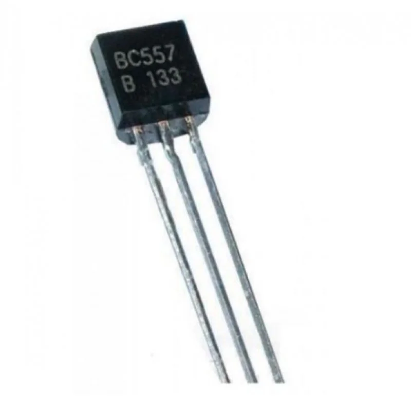
BC557 PNP General Purpose Transistor – TO-92-3 Package
[Transistor] BC557 PNP General Purpose Transistor – TO-92-3 Package BC557 PNP General Purpose Transistor 45V 100mA BC557 is a semiconductor device used to amplify or switch electronic signals and electrical power. This transistor composed of semiconductor material usually with at least three terminals for connection to an external circuit. A voltage or current applied to one pair of the transistor’s terminals controls the current through another pair of terminals. Because the controlled (output) power can be higher than the controlling (input) power, a transistor can amplify a signal. This product is known as BC557, BC557BTA, BC557ATA, BC557BTF, BC557B, BC557C, BC557A, BC557CBK, BC557BBK Features: Low current (max. 100 mA) Low voltage (max. 65 V). Low error voltage Fast switching speed Full-voltage operation High power and current handling capability Features/Specs: Product Type: BJTs – Bipolar Transistors Transistor Polarity: PNP Configuration: Single Collector- Emitter Voltage VCEO Max: 45 V Collector- Base Voltage VCBO: 50 V Emitter- Base Voltage VEBO: 5 V Pd – Power Dissipation: 500 mW Gain Bandwidth Product fT: 100 MHz DC Collector/Base Gain hFE Min: 125 DC Current Gain hFE Max: 125 at 2 mA, 5 V Minimum Operating Temperature: – 65°C Maximum Operating Temperature: + 150°C Mounting Style: Through Hole Package/Case: TO-92-3 Applications: Driver Modules like Relay Driver, LED driver etc.. Amplifier modules like Audio amplifiers, signal Amplifier etc.. Darlington pair Datasheet: BC557 PNP Transistor Package Includes: 1 x BC557 PNP General Purpose Transistor – TO-92-3 Package Note: Product Images are shown for illustrative purposes only and may differ from actual product
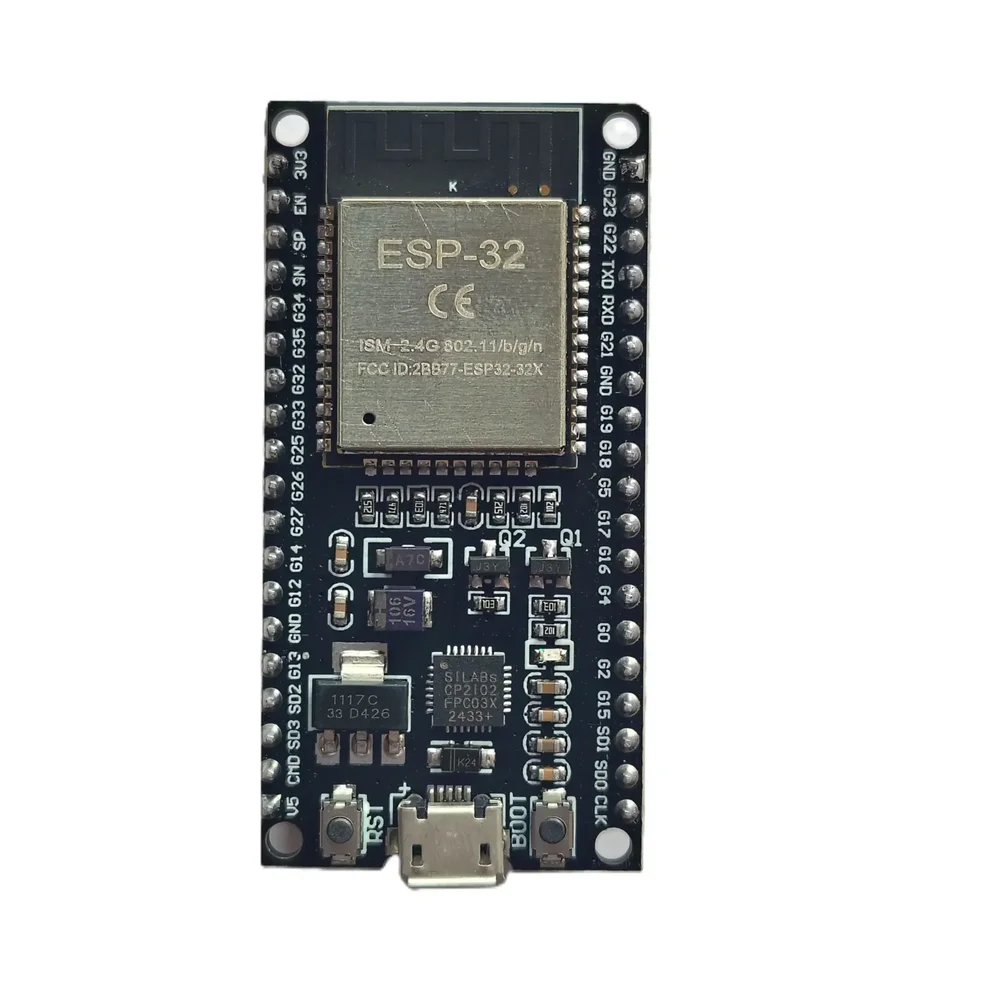
ESP32 38-Pin Development Board – IoT Microcontroller with WiFi & Bluetooth
[ESP Modules] Description The ESP32 38-Pin Development Board is a versatile and cost-effective microcontroller platform perfect for a wide range of IoT, automation, and wireless communication projects. Powered by the ESP32 SoC, this board offers integrated WiFi and Bluetooth (BLE) capabilities, making it ideal for developing smart home devices, industrial control systems, robotics, and DIY electronics. For the best IoT experience, you can pair this board with our LoRa SX1278 Module for long-range communication or integrate it with our 0.96-inch OLED Display for real-time data display. Need reliable power control? Combine it with our 2-Channel Relay Module with Optocoupler for safe switching of external devices. Compatible with popular platforms like Arduino IDE, MicroPython, and PlatformIO, this ESP32 board is user-friendly for both beginners and professionals. The board features 38 GPIO pins, enabling you to connect a variety of sensors, actuators, and other peripherals—available in our IoT Components category. Key Features: ESP32 Dual-Core 32-bit LX6 Processor Built-in 2.4 GHz WiFi and Bluetooth 4.2 (BLE) 38 GPIO Pins supporting multiple digital and analog functions Interfaces: UART, SPI, I2C, PWM, ADC, DAC Ultra-low power operation modes ideal for battery-powered IoT devices Supports Arduino IDE, MicroPython, and other environments Onboard micro-USB connector for easy power and programming Reset and boot buttons for firmware flashing Breadboard-friendly form factor Applications: IoT development projects Smart home automation – compatible with Vihaan IoT Gateway Solutions Wireless data logging systems Robotics and drone controllers Industrial monitoring devices Sensor networks – connect with our DHT11/DHT22 Temperature Sensors Specifications: Chipset: ESP32 (Generic) Operating Voltage: 3.3V (5V tolerant inputs) Flash Memory: 4MB Connectivity: WiFi IEEE 802.11 b/g/n, Bluetooth 4.2 BLE Interfaces: GPIO, UART, SPI, I2C, ADC, DAC, PWM USB Interface: Micro USB Form Factor: 38-Pin, breadboard compatible Package Includes: 1 x ESP32 38-Pin Generic Development Board
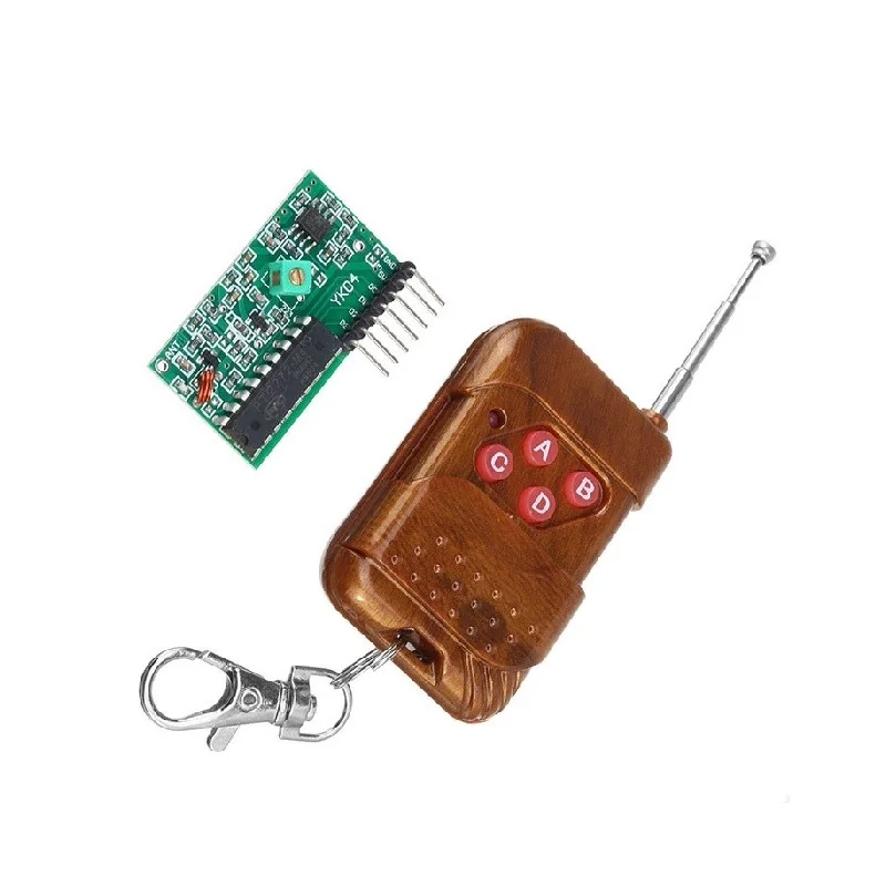
315MHz 4 Channel Wireless RF Remote Control Kit with Receiver Module (Non-Locking Mode)
[RF Module] 📡 315MHz 4 Channel Wireless RF Remote Control Kit with Receiver Module (Non-Locking Mode) 4 Channel RF Remote • 315MHz ASK Communication • 5V Receiver • Non-Locking Mode • Long Range Wireless Control The 315MHz 4 Channel Wireless RF Remote Control Kit is a reliable wireless control solution consisting of a 4-button RF transmitter and a super regenerative ASK receiver module. Operating at 315MHz, this kit is ideal for remote switching, automation, robotics, security systems, and DIY wireless control projects. The receiver module features four independent digital outputs (D0–D3) that correspond to the four buttons on the transmitter. When a button is pressed, the respective output pin goes HIGH, returning LOW immediately after the button is released. This Non-Locking (Momentary/Jog) operation makes the module perfect for applications requiring temporary switching such as electric door control, motor jogging, relay activation, and microcontroller interfacing. The receiver operates from a 5V DC supply and features a high-sensitivity ASK receiver with a Valid Transmission (VT) output pin for reliable signal detection. The transmitter uses a fixed-code encoder for secure communication and easy operation. Ideal for Arduino, ESP32, Raspberry Pi, AVR, PIC, industrial automation, wireless switching, and educational electronics projects. ⭐ Features 4-channel wireless RF remote control kit Operating frequency: 315MHz ASK (Amplitude Shift Keying) modulation Fixed-code RF transmitter Non-Locking (Momentary/Jog) operating mode Four independent digital outputs (D0–D3) High-sensitivity super regenerative receiver 5V DC receiver operating voltage VT (Valid Transmission) status output Compact PCB design Easy interface with microcontrollers Long wireless transmission range (environment dependent) Suitable for DIY and industrial automation 📋 Technical Specifications RF Transmitter Product Type: RF Wireless Remote Control Operating Frequency: 315MHz Number of Buttons: 4 Channels: 4 Modulation: ASK (Amplitude Shift Keying) Encoding Type: Fixed Code Operating Mode: Non-Locking (Momentary) Power Supply: 12V A23 Battery (Not Included) RF Receiver Module Operating Voltage: 5V DC Operating Frequency: 315MHz Receiver Type: Super Regenerative ASK Receiver Receiver Sensitivity: -98dBm Output Channels: D0, D1, D2, D3 VT Output: Yes (Valid Signal Output) Antenna Connection: External ANT Pin Recommended Antenna Length: Approx. 17cm (Quarter-Wave) Module Dimensions: Approx. 41 × 22 × 7 mm Receiver Pin Configuration VT – Valid Signal Output D3 – Channel 4 Output D2 – Channel 3 Output D1 – Channel 2 Output D0 – Channel 1 Output +5V – Power Input GND – Ground ANT – External Antenna Connection 🔧 Operating Modes Non-Locking (Momentary/Jog Mode) Press a button → Corresponding output goes HIGH. Release the button → Output immediately returns LOW. Ideal for momentary control applications. Note: This product is supplied in Non-Locking Mode only. 🔧 Applications Suitable for: Arduino Projects ESP32 Projects Raspberry Pi Projects Wireless Relay Control Home Automation Industrial Automation Remote Door Control Electric Door Locks Wireless Switching Robotics Motor Control Lighting Control Alarm Systems Security Systems DIY Electronics Educational Projects 📦 Package Includes 1 × 4-Button 315MHz RF Wireless Remote Control 1 × 315MHz Super Regenerative Receiver Module ⚠️ Note Battery is included. A 12V A23 battery is required for operation. Avoid bending or touching the receiver's onboard inductor (copper coil), as this may affect receiver sensitivity. Wireless operating range depends on antenna quality, obstacles, and surrounding RF interference. Product appearance may vary slightly depending on the manufacturing batch.
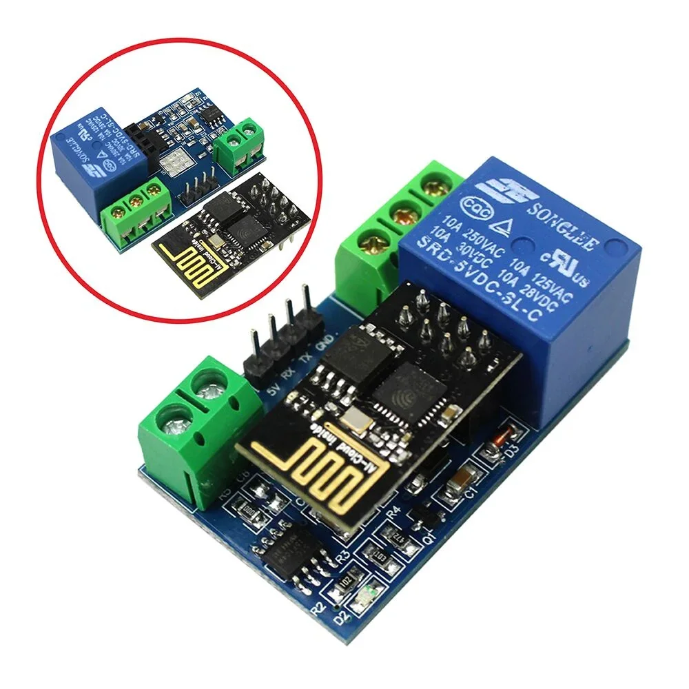
ESP8266 WiFi 5V 1 Channel Relay Module Good Quality
[Relay Module] General Info : Onboard ESP8266 WIFI module, AP mode can be connected at the same time 5 client The module has two ways to work: (i) mobile phone directly mounted on the WIFI module; (ii) mobile phone and WIFI module also carried on the router. How to use : Onboard ESP8266 WIFI module has three operating modes: STA (client), AP (hot), STA + AP (client + hot), according to the work of the module to select the corresponding WIFI module mode of operation The The module needs to use the serial debugging software on the computer and USB to TTL module to send AT commands to configure the WIFI module, USB to TTL module RX, TX, GND pin, then the module on the TX, RX, GND pin, IN +, IN – 5V power supply. Usage Instructions 1) Hardware Connection: Insert the pre-programmed ESP-01/01S module into the onboard 2×4 pin female header (as shown in the diagram below). 2) Power Supply : Connect a DC 5V-12V power source to the module, with the positive terminal to VCC and the negative terminal to GND. 3) Mobile WiFi Connection : Open your phone's WLAN settings, search for and connect to the ESP8266-XXXX hotspot (default password: 12345678). 4) Launch Control APP : Run the pre-installed ESP8266 Controller application on your Android phone. 5) Configure IP Address : Enter the default IP address: 192.168.1.1 in the APP to remotely control the relay switch via your phone. Transmission distance: Open environment, the mobile phone mounted on the WIFI module when the maximum transmission distance of 400m. When the WiFI module and mobile phone at the same time carried on the router when the transmission distance according to the router’s signal weakly; Board function description : IN +, IN-: 5V power input; TX, RX, GND: Serial debug pin; Onboard the ESP8266 WIFI module has three work modes: STA (client), AP (hot), the STA + Ap( hot +client), according to the workings of a module to the corresponding choice of WIFI module working mode. Module need before use serial debugging software and USB to TTL module send serial command was carried out on the WIFI module configuration (don’t power outages after configuration is complete, as some of the parameters of WIFI module cannot be saved when the power is cut off), mobile phone and WIFI module after establishing a network connection can use the phone APP control relay. Control Commands : When cell phone equipped with WiFi module sends commands in the following order: (The default baud rate 115200) AT+CWMODE=2, namely AP mode is selected. AT+RST, reset. AT+CIPMUX=1, open multiple connections. AT+CIPSERVER=1,8080, configure the TCP server, set the port. AT+CIOBAUD=9600 set the baud rate to 9600. (working in relays to control the baud rate 9600). AT+CIFSR to view the AP mode IP address, such as the APIP, “192.168.4.1”. Cell phone WIFI signal connection name starts with AI-THINKER or ESP8266. In the “TCP connection” address and port into the APP, such as 192.168.4.1 and 8080. Click on the grey box relays can be controlled. Features: Onboard Module: ESP8266 wifi module; in AP mode it can connect with 5 Clients at the same time Operating Way: cellphone carried on wifi module; cellphone and wifi module carried on the same router, and use the APP to control relay Diode effusion protection. Short response time
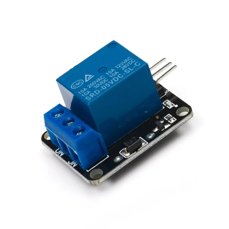
1-Channel 5V Relay Module for Arduino
[Relays] This is 1 Channel 5V Relay Board Module For Arduino PIC AVR DSP ARM. A wide range of microcontrollers such as Arduino, AVR, PIC, ARM and so on can control it. Each one needs 15mA – 20mA driver current and Equipped with high current relay: DC 5V / 10A, AC 250V / 10A Standard interface that can be compatible with microcontroller. Specification and Features :- 1 channel 5v relay board Operating Voltage : 5V Max Current : 20mA Relay Contact Current Capacity at AC250V: 10A Relay Contact Current Capacity at DC5V: 10A One normally closed contact and one normally open contact Triode drive, increasing relay coil High impedance controller pin Pull-down circuit for avoidance of malfunction Power supply indicator lamp Control indicator lamp Indicator for Relay output status Can Be controlled various appliances & other Equipment With Large current. Standard TTL Level logic controlled (AVR, Arduino, 8051, PIC, ARM) The module is compliant with international safety standards, control and load areas isolation trenches; * Product Images are shown for illustrative purposes only and may differ from actual product.
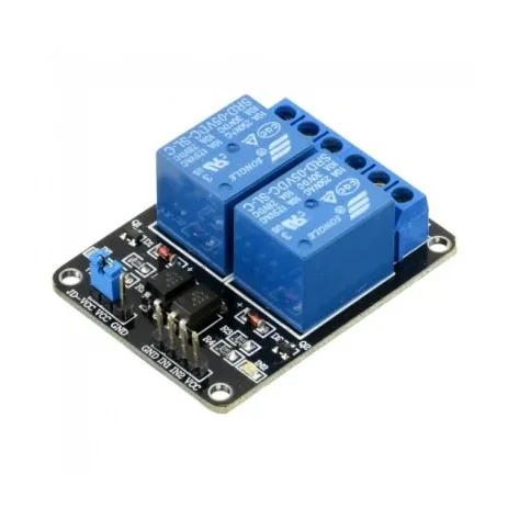
2 Channel 5V Relay Module with Optocoupler
[Relays] This is a 5V, 10A 2-Channel Relay interface board. It can be used to control various appliances, and other equipments with large current. It can be controlled directly with 3.3V or 5V logic signals from a microcontroller (Arduino, 8051, AVR, PIC, DSP, ARM, ARM, MSP430, TTL logic). It has a 1×4 (2.54mm pitch) pin header for connecting power (5V and 0V), and for controlling the 2 relays. The pins are marked on the PCB:- GND – Connect 0V to this pin. IN1 – Controls relay 1, active Low Relay will turn on when this input goes below about 2.0V IN2 – Controls relay 2, active Low Relay will turn on when this input goes below about 2.0V VCC – Connect 5V to this pin. Is used to power the opto couplers Specification:- High current relay, AC250V 10A, DC5V 10A 2 LEDs to indicate when relays are on Works with logic level signals from 3.3V or 5V devices Opto isolation circuitry * Product Images are shown for illustrative purposes only and may differ from actual product.
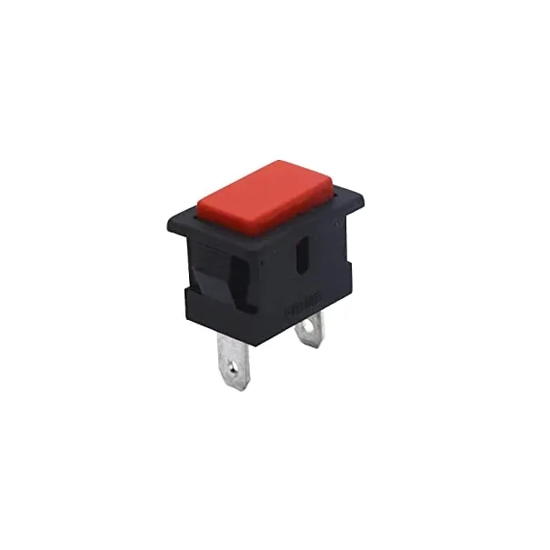
SPST Momentary Rectangular Horn Type Push Button Switch – Red
[Mechanical Switches] SPST Momentary Rectangular Horn Type Push Button Switch – Red The SPST Momentary Rectangular Horn Type Push Button Switch (Red) is a durable and reliable momentary push-to-ON switch designed for horn, alarm, buzzer, control, and general-purpose switching applications. The switch completes the electrical circuit only while the button is pressed and automatically returns to the OFF state when released. Its rectangular horn-type button provides a convenient pressing surface, while the red actuator offers high visibility for applications where quick identification of the control is important. The panel-mount design allows easy installation in control panels, vehicles, enclosures, and DIY projects. ⭐ Key Features SPST (Single Pole Single Throw) Momentary push-to-ON operation Spring-return action Rectangular horn-type button Red button Panel-mount design Durable construction Reliable contact performance Easy to operate Suitable for horn and alarm applications 📋 Technical Specifications Product Type: Momentary Push Button Switch Switch Type: SPST Operation: Momentary / Spring Return Contact Action: Push-to-ON Button Shape: Rectangular Horn Type Button Color: Red Mounting Type: Panel Mount Number of Poles: Single Pole Number of Throws: Single Throw Application: Horn / Alarm / Control Contact Type: Momentary Note: The supplied product information does not specify the voltage rating, current rating, dimensions, terminal type, or mechanical/electrical life, so these specifications should be verified against the exact product variant before listing them. 🔧 Applications Vehicle Horn Switch Car Horn Bike Horn Marine Horn Alarm & Buzzer Control Industrial Control Panels Start / Stop / Reset Functions DIY Electronics Projects Consumer Electronics Testing Equipment Temporary Circuit Activation 🛠️ Installation Install the switch through a suitable panel cutout and secure it firmly. Connect the switch terminals according to the required circuit. Since this is a momentary push-to-ON switch, the circuit is active while the button is pressed and returns to its normal OFF state when released. 📦 Package Includes 1 × SPST Momentary Rectangular Horn Type Push Button Switch – Red ⚠️ Precautions Verify the switch's voltage and current rating before connecting a load. Disconnect the power supply before installation or wiring. Ensure terminals and wiring are properly secured. Do not exceed the manufacturer's electrical ratings. For vehicle or industrial applications, use an appropriate relay where the load current exceeds the switch rating. Product images are for illustration purposes only and actual appearance may vary.
 Out of stock
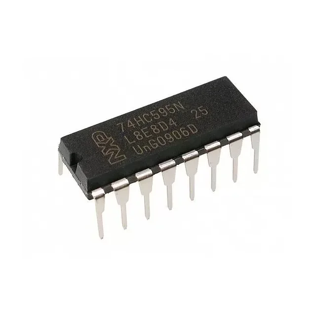
74HC595 Serial to Parallel Shifting IC
[Logic Gates IC] DESCRIPTION:- The 74HC595N is a simple 8-bit shift register IC. Simply put, this shift register is a device that allows additional inputs or outputs to be added to a microcontroller by converting data between parallel and serial formats. Your chosen microprocessor is able to communicate with The 74HC595N using serial information then gathers or outputs information in a parallel (multi-pin) format. Essentially it takes 8 bits from the serial input and then outputs them to 8 pins. This small DIP packaged IC contains an 8-bit, serial-in-parallel-out shift register that feeds an 8-bit D-type storage register with parallel 3-state outputs. Pin Configuration:- Pin Number Pin Name Description 1,2,3,4,5,6,7 Output Pins (Q1 to Q7) The 74hc595 has 8 output pins out of which 7 are these pins. They can be controlled serially 8 Ground Connected to the Ground of the circuit 9 (Q7) Serial Output This pin is used to connect more than one 74hc595 as cascading 10 (MR) Master Reset Resets all outputs as low. Must be held high for normal operation 11 (SH_CP) Clock This is the clock pin to which the clock signal has to be provided from MCU/MPU 12 (ST_CP) Latch The Latch pin is used to update the data to the output pins. It is active high 13 (OE) Output Enable The Output Enable is used to turn off the outputs. Must be held low for normal operation 14 (DS) Serial Data This is the pin to which data is sent, based on which the 8 outputs are controlled 15 (Q0) Output The first output pin. 16 Vcc This pin powers the IC, typically +5V is used. Features :- 8-bit, Serial In – Parallel out Shift register Operating Voltage: 2V to 6V Power Consumption: 80uA Output source/sink current: 35mA Output Voltage is equal to Operating voltage Minimum high-level Input Voltage: 3.15V @(Vcc=4.5V) Maximum low-level Input Voltage: 1.35V @(Vcc=4.5V) Can be easily cascaded with more IC to get more outputs Maximum Clock Frequency: 25Mhz @4.5V Available in 16-pin PDIP, GDIP, PDSO packages Where to Use 74HC595 IC:- The 74HC595 is an 8-bit Serial In – Parallel Out Shift Register, i.e. it can receive (input) data serially and control 8 output pins in parallel. This comes in very handy where do not have enough GPIO pins on our MCU/MPU to control the required number of outputs. It is often used in projects where relatively a large number of LED's has to be controlled through the Microcontroller. It can also be used to interface LCD screen since they can acts as the data bit for the LCD displays. It can also be used to control 5V loads like relays through a 3.3V microcontroller since the high-level voltage is only 3.15. So if you are looking for an IC to save on your GPIO pins on the Microcontroller then this IC might be the right choice for you. How to Use a 74HC595 IC:- The 74HC595 shift register is commonly used with microcontrollers or microprocessors to expand the GIPO functionalities. It requires only 3 pins connected to the MCU, which are Clock, Data and Latch. It has a wide operating voltage from 2V to 6V. An application circuit of the IC is shown below: Package Includes:- 1 x 74HC595 IC
 Out of stock
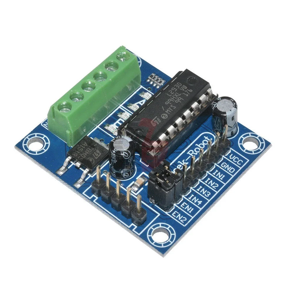
Mini Motor Drive Shield Expansion Board L293D Module for Arduino UNO MEGA 2560
[Brushed DC motor Driver] Mini Motor Drive Shield Expansion Board L293D Module for Arduino UNO MEGA 2560 is a Device is a monolithic integrated high voltage, high current four channel driver designed to accept standard DTL or TTL logic levels and drive inductive loads (such as relays solenoids, DC and stepping motors) and switching power transistors. To simplify use as two bridges each pair of channels is equipped with an enable input. A separate supply input is provided for the logic, allowing operation at a lower voltage and internal clamp diodes are included. This device is suitable for use in switching applications at frequencies up to 5 kHz. Features: Enable facility. Overtemperature protection. Logical “0” input voltage up to 1.5V(High noise immunity). Internal clamp diodes. Package Includes: 1 x Mini Motor Drive Shield Expansion Board L293D Module.
 Out of stock
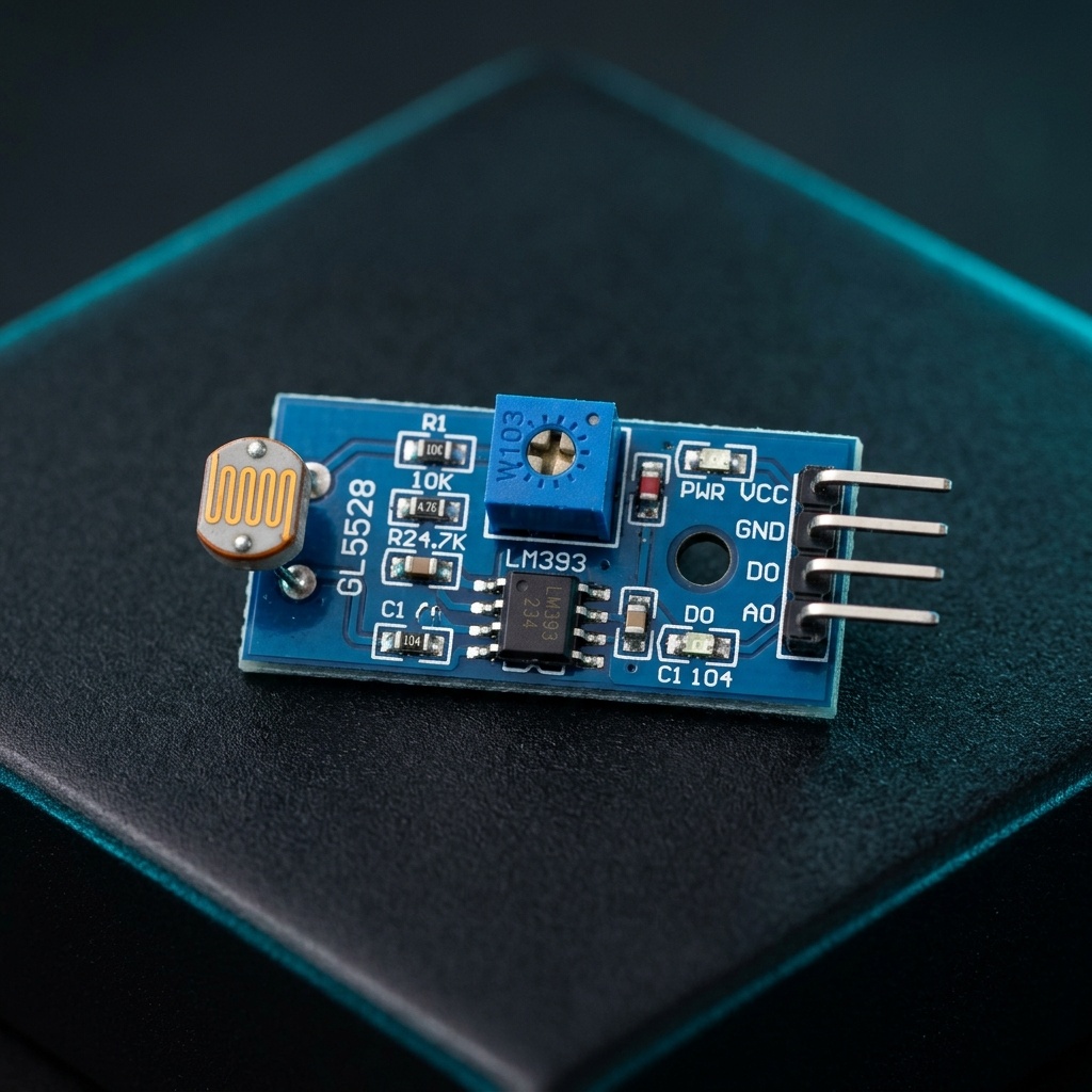
Digital LDR Module
[Light Sensors] The Digital LDR Module is used to detect the presence of light / measuring the intensity of light. The output of the module goes high in the presence of light and it becomes low in the absence of light. The sensitivity of signal detection can be adjusted using the potentiometer. Use it to detect the light brightness in your environment and decide to switch OFF or ON light? Or maybe to adjust the brightness of the LED of your house? You can adjust the threshold (sensitivity) of the digital output by tuning the onboard variable resistor (potentiometer). Simple usage as it is the digital output, so you will know is the light present and decide what to do with it. It comes with an M3 mounting hole for ease of attaching it to an object. Onboard, it provides an LDR, high sensitivity and commonly being used for light detection. The module comes with a power LED and a status LED as an indicator. LDR Module Photosensitive resistor module most sensitive to environmental light intensity is generally used to detect the ambient brightness and light intensity. Features – LM393 based design. Can detect ambient brightness and light intensity. Adjustable sensitivity (via blue digital potentiometer adjustment). Output Digital – 0V to 5V, Adjustable trigger level from preset. LEDs indicating output and power. Operating Voltage: 3.3V to 5V DC. Operating Current: 15ma. How it works 1. Module light conditions or light intensity reach the set threshold, DO port output high when the external ambient light intensity exceeds a set threshold, the module D0 output low; 2. Digital output D0 directly connected to the MCU, and detect high or low TTL, thereby detecting ambient light intensity changes; 3. Digital output module DO can directly drive the relay module, which can be composed of a photoelectric switch. Pin details VCC ↔ 3.3V to 5V DC. GND ↔ Ground. DO ↔ Digital Output.
 Out of stock
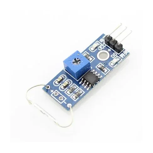
Magnetic Reed Switch Sensor Module
[Magnetic Sensor] Magnetic Control Module Reed Switch Sensor This module can be applied in Program-controlled switches, copiers, washing machines, refrigerators, cameras, Disinfection cabinets, doors, window magnetic, electromagnetic relays, electronic weighing, level meters, gas meters, water meters, and so on. Specifications and Features: Clean, good waveform driving ability, more than 15mA. Working voltage 3.3V-5 Output format: digital switching output (0 and 1) A fixed bolt hole for easy installation PCB size: 3.2cm x 1.4cm Digital output using a voltage LM393 comparator IC Package Includes: 1 x Reed Switch Module
 Out of stock
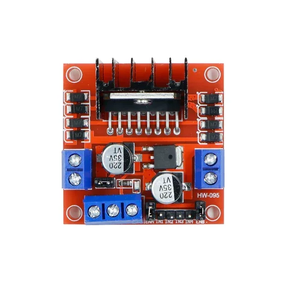
L298N 2A Based Motor Driver Module
[Brushed DC motor Driver] L298 Motor Driver Module | 2A Dual Channel PWM Control L298 Motor Driver Module, 2A Dual Channel total 4A, PWM Control for motors variable speed, with back EMF protection, versatile for Robotics Arduino Raspberry PI. It is a high voltage, high current, dual full-bridge motor driver designed to accept standard TTL logic levels and drive inductive loads such as relays, solenoids, DC and stepping motors. Current Sense for each motor. Heatsink for better performance. Power-On LED indicator. Driver chip: L298 dual H-bridge driver chip. Operates up to 35V DC Drive part of the peak current Io: 2A / Bridge Logical part of the terminal power supply range Vss :4.5V-5.5V Logical part of the operating current range: 0 ~ 36mA Maximum power consumption: 20W
 Out of stock
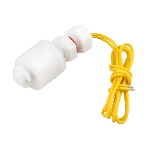
ZP4510 P45 Water Level Sensor Float Control Switch
[Water Level Sensor] A float switch is a device used to sense the level of liquid within a tank, it may actuate a pump, an indicator, an alarm, or another device. A float switch is a device used to sense the level of liquid within a tank. The switch may actuate a pump, an indicator, an alarm, or another device. Use them with hydroponics, saltwater tank, freshwater tank, gardening, aquariums for power head control, pet bowls, fish tanks, filtration, heating, pumps, ponds, basement alarms, boats, air condition drain pans, pressure washers, carpet cleaning machine, reef aquarium, fluid control, ice machines, coffee pots, marine, automotive, automobiles, tropical fish tanks, evaporator coils, condensation line, in relays, or whatever your project may be. It can be easily converted from normally open to normally close by inverting the float. Note: because the current that the switch can carry is much little(0.5A), you must use a relay or contactor when it is connected by a load, relay and contactor are not included here. Specifications:- Cable Length: 30.5(cm) Maximum Load: 50 W Max Switching Voltage: 100V DC Minimum Voltage: 250V DC Maximum Switching Current: 0.5 A Max Load Current: 1.0 A Max Contact Resistance: 0.4 ΩTemp Rating: -20~ 80 degree Applications:- Household Equipment such as overhead water tanks, Water purifiers. Use them with hydroponics, saltwater tank, freshwater tank, gardening, aquariums for power head control, pet bowls, fish tanks, filtration, heating, or whatever your project may be. Up float switch Contains no mercury Product. How Magnetic Reed Liquid Level Sensors Work:- The purpose of a float switch is to open or close a circuit as the level of a liquid rises or falls. Most float switches are "normally closed," meaning the two wires coming from the top of the switch complete a circuit when the float is at its low point, resting on its bottom clip or stop (for example, when a tank is dry). Most float switches utilize a magnetic reed switch to open or close the circuit. The reed is encased in a glass tube, which is cemented into a plastic or stainless steel stem with epoxy. The illustration to the left demonstrates how a magnet can be used to open or close a circuit by moving it closer to or farther away from a reed switch. When the magnet comes close to the two contacts, they draw together and touch, allowing the current to pass through. When the magnet is moved away, the contacts demagnetize and separate, breaking the circuit. In a float switch, the magnetic reed switch is hermetically sealed in a stem, most often made from plastic or stainless steel. The float encases a sealed magnet, which moves up and down the length of the stem as a fluid level rises and falls. As the magnet passes by the contacts in the encased reed switch, they draw together and complete a circuit between the two lead wires. The operation shown can usually be reversed by removing the bottom clip from the switch, inverting the float, and replacing the clip. When this change is made, the switch circuit will be open when the float is resting on the bottom clip and closed when the float rises. Properly used, float switches can deliver millions of on/off cycles, for years of dependable operation. Failures are normally due to overloading, frequently caused by spiking voltage. Before designing a circuit that uses a float switch, be sure to read our Technical Page on Spiking Voltage & Float Switches. * Product Images are shown for illustrative purposes only and may differ from the actual products.
 Out of stock
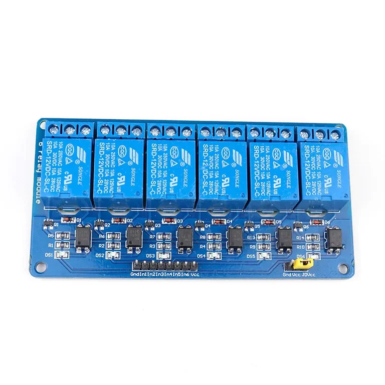
12V 6 Channel with Light Coupling Relay Module
[Relay Module] This 6 Road/Channel Relay Module (with light coupling) 12V module meets the safety standard as control areas and load area have the isolation groove. Optical coupling isolation module. The triggering of the 6 Road/Channel Relay Module is reliable, more stable. The double FR–4 circuit board design, high-end SMT process. It has power and relay operation instructions. Relays terminals (C, NC, NO) are accessible through screw terminals which makes wiring up the board very easy. The inputs of the 8 Channel 12V Relay Module are isolated to protect any delicate control circuitry. A wide range of microcontrollers such as Arduino, AVR, PIC, ARM and so on can control it. The use of such high-voltage relay eliminates the risk of heating up of the relay as electromechanical relay limit the current consumption in accordance with a voltage rating. Module interface: The positive (according to the relay voltage VCC: connect power supply) GND: connect power negative IN1: relay module (effective) high-level trigger signal trigger end IN2: relay module (effective) high-level trigger signal trigger end IN3: relay module (effective) high-level trigger signal trigger end IN4: relay module (effective) high-level trigger signal trigger end IN5: relay module (effective) high-level trigger signal trigger end IN6: relay module (effective) high-level trigger signal trigger end IN7: relay module (effective) high-level trigger signal trigger end IN8: relay module (effective) high-level trigger signal trigger end Meaning of High level and Low-level High-level trigger refers to using the anode voltage at the VCC connection way of a trigger and triggers the end when the trigger side has a positive voltage or to trigger voltage when the relay is off. Low-level trigger refers to using the negative voltage at the GND connection way of a trigger and triggers the end when the trigger side has 0 v low voltage or voltage to can trigger, the relay is off. Features : Equipped with high-current relay 10A@250VAC / 10A@30VDC It can control both AC and DC appliances such as Solenoids, Motors, lights, fans, etc High-quality screw terminals (Terminal Block) provided (C, NC, NO) for quick and easy connection A freewheeling diode to protect your microcontroller Input Signal Pin connected to Burg stick for easy accessibility LED status indicators to indicate the relay ON/OFF status Mounting holes provided Signal input with a high-level signal, the common and often start conduction; The relay can directly control all kinds of equipment and load; One often opened a normally closed contact; Blue KF301 terminal line more convenient. It is also able to control various appliances and other types of equipment with a large current. Red working status indicator lights are conducive to safe use. Widely used for all MCU control, industrial sector, PLC control, smart home control. Package Includes: 1 x 12V 6 Channel with Light Coupling Relay Module
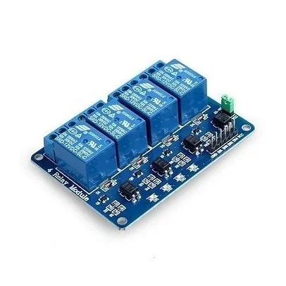
4 Channel Isolated 5V 10A Relay Module opto coupler For Arduino PIC AVR DSP ARM
[Relay Module] The 4 Channel Isolated 5V Relay Module is a reliable switching interface that enables low-voltage microcontrollers to safely control high-voltage and high-current electrical devices. Featuring four independent relays with opto-isolation, the module provides excellent electrical separation between the control circuitry and load side for enhanced safety and reliability. In addition, each relay can be individually controlled through dedicated input pins, allowing multiple devices to be switched independently. As a result, the module is ideal for home automation, industrial control systems, robotics, IoT projects, and appliance control applications. Because of its opto-coupler isolation design, the relay board helps protect sensitive microcontrollers from electrical noise and voltage spikes. Furthermore, onboard status LEDs provide clear indication of relay activation and power status. The module supports both AC and DC load switching, making it suitable for controlling lamps, fans, pumps, motors, solenoids, and various household appliances. Moreover, the high-quality relay contacts ensure reliable long-term operation under demanding conditions. This relay module is widely used in Arduino projects, Raspberry Pi automation systems, PLC control panels, industrial automation, smart home systems, and embedded electronics applications. 🔹 Key Features 4 independent relay channels Opto-isolated input design Supports high and low level triggering Compatible with Arduino, Raspberry Pi, ESP32, PIC, AVR, ARM, and PLC High-current relay contacts LED power and relay status indicators Electrical isolation between control and load circuits Suitable for AC and DC load switching Easy interfacing with microcontrollers Industrial-grade design 🔹 Technical Specifications Product Type: 4 Channel Relay Module Operating Voltage: 5V DC Number of Channels: 4 Relay Type: JQC3F-5VDC-C / SRD-05VDC-SL-C / FL-3FF-S-Z (Random) Contact Configuration: SPDT (NO, COM, NC) Maximum AC Load: 250V AC, 10A Maximum DC Load: 30V DC, 10A Trigger Voltage: Approx. 1V – 5V Isolation Method: Opto-Coupler Isolation Input Interface: Standard TTL Control Signal Trigger Mode: High-Level / Low-Level Trigger Status Indicators: Power LED and Relay LEDs Mounting Holes: Yes 🔹 Pin Configuration Control Side VCC – 5V Power Supply GND – Ground IN1 – Relay Channel 1 Control IN2 – Relay Channel 2 Control IN3 – Relay Channel 3 Control IN4 – Relay Channel 4 Control Relay Output Terminals For each channel: COM – Common Terminal NO – Normally Open Contact NC – Normally Closed Contact 🔹 Applications This relay module is suitable for: Arduino projects Raspberry Pi projects ESP32 projects Home automation systems Industrial automation PLC control systems Smart home devices Lighting control Motor and pump control Appliance switching IoT projects 🔹 Package Includes 1 × 4 Channel 5V 10A Opto-Isolated Relay Module