
All products · 20 of 1440
Electronics, sensors, robotics kits, PC components, peripherals — everything Unik Systems carries, in one place.

IOT Plug & Play
MCU: ESP8266/ESP32 based (Wi-Fi 2.4GHz). Supply: 5V input, onboard 3.3V regulation. Protocols: MQTT/HTTP. Cloud/App support. GPIO with pre-wired ports. Typical sensors: DHT11/22, LDR, relay module, IR, PIR.
 Only 1 left
IOT Smarthome Kit
MCU: ESP8266/ESP32. Modules: 1–4 channel relay (optocoupled preferred), PIR, LDR, DHT. Control: app/web dashboard. Protocols: MQTT/HTTP. Power: 5V input. Properly isolated AC relay use.
 Only 1 left
Play Mex
MCU: ESP8266/ESP32. Sensors: soil moisture (capacitive preferred), temp/humidity (DHT), light sensor. Actuation: relay/pump/solenoid valve demo. Dashboard: MQTT/HTTP. Power: 5V input + relay isolation.
 Out of stock
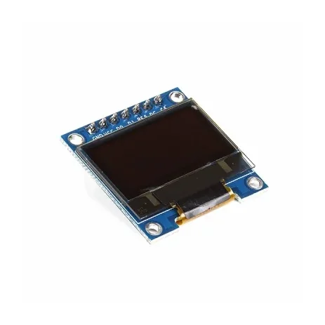
0.96 Inch Blue SPI OLED Display Module 7-Pin 128×64 – SSD1306
[LED/LCD Display] 0.96 Inch Blue SPI OLED Display Module 7-Pin 128×64 – SSD1306 The 0.96-inch Blue OLED Display Module is a compact graphical display based on the SSD1306 driver IC, featuring a 128×64 pixel resolution and blue monochrome display. This version has a 7-pin interface with a dedicated CS (Chip Select) pin, making it suitable for 4-wire SPI communication. The module is factory-configured for SPI and can also be modified for I2C/IIC communication on compatible board versions. With its compact size, wide viewing angle and low-power OLED technology, it is suitable for Arduino, ESP32, ESP8266, STM32, Raspberry Pi and other microcontroller projects. ⭐ Key Features 0.96-inch blue OLED display 128 × 64 pixel resolution SSD1306 driver IC 7-pin interface Dedicated CS (Chip Select) pin Factory configured for 4-wire SPI Supports SPI and I2C/IIC with appropriate configuration 3.3V/5V compatible on supported module versions No backlight required Low power consumption Wide viewing angle of more than 160° Compact PCB design Pre-soldered 7-pin male header Compatible with Arduino, ESP32, ESP8266, STM32 and Raspberry Pi projects 📋 Technical Specifications Display Type: OLED (Organic Light-Emitting Diode) Display Colour: Blue Display Size: 0.96 inch Driver IC: SSD1306 Resolution: 128 × 64 pixels Interface: SPI / I2C Default Interface: 4-wire SPI Input Voltage: 3.3V–5V Viewing Angle: >160° Module Dimensions: Approximately 27 × 27 × 4mm Operating Temperature: Approximately -30°C to +70°C Header: 7-pin male header, pre-soldered Display Type: Monochrome blue OLED 🔌 7-Pin Interface The 7-pin version provides the following connections: GND – Ground VCC – Power supply D0 / SCK / CLK – SPI clock D1 / MOSI / SDA – SPI data RES / RST – Display reset DC / A0 – Data/Command selection CS – Chip Select 🛠️ SPI Connection The module is normally supplied in 4-wire SPI configuration. For an Arduino Uno, a typical connection is: VCC → 5V GND → GND D0 → SCK / D13 D1 → MOSI / D11 RES → Digital I/O DC → Digital I/O CS → Digital I/O The dedicated CS pin allows the OLED to share the SPI bus with other devices such as SD cards or additional SPI peripherals. 🔄 I2C / IIC Configuration On compatible versions, the module can be converted from SPI to I2C by changing the appropriate resistor configuration on the PCB. The supplied board configuration may require: Moving the resistor from R3 to R1 Shorting R8 with solder Using D0 as SCL Using D1 as SDA Configuring DC for the I2C address The exact resistor positions can vary between board revisions, so check the markings on your particular PCB before modification. 🎯 Applications Arduino projects ESP32 projects ESP8266 projects STM32 development Raspberry Pi projects IoT devices Sensor displays Voltage/current meters Battery monitors Temperature displays Digital clocks Data loggers Portable electronic devices Robotics DIY measuring instruments Embedded systems Menu and status displays 💡 Advantages of OLED OLED technology is self-emissive, meaning the pixels produce their own light and do not require a conventional backlight. This provides high contrast, compact construction and a wide viewing angle while keeping power consumption relatively low. ⚠️ Important Notes This is the 7-pin SPI version, not the 6-pin version. The module is normally configured for SPI communication. Check the PCB labels before connecting the module. Do not exceed the specified supply voltage. Although many versions support 5V operation, the exact voltage tolerance can vary between board revisions. I2C operation may require hardware resistor modification. The actual PCB layout and component markings may vary slightly between production batches. Display colour: Blue. Libraries such as Adafruit SSD1306 and U8g2 can be used with compatible microcontrollers. 📦 Package Includes 1 × 0.96 Inch Blue SPI OLED Display Module
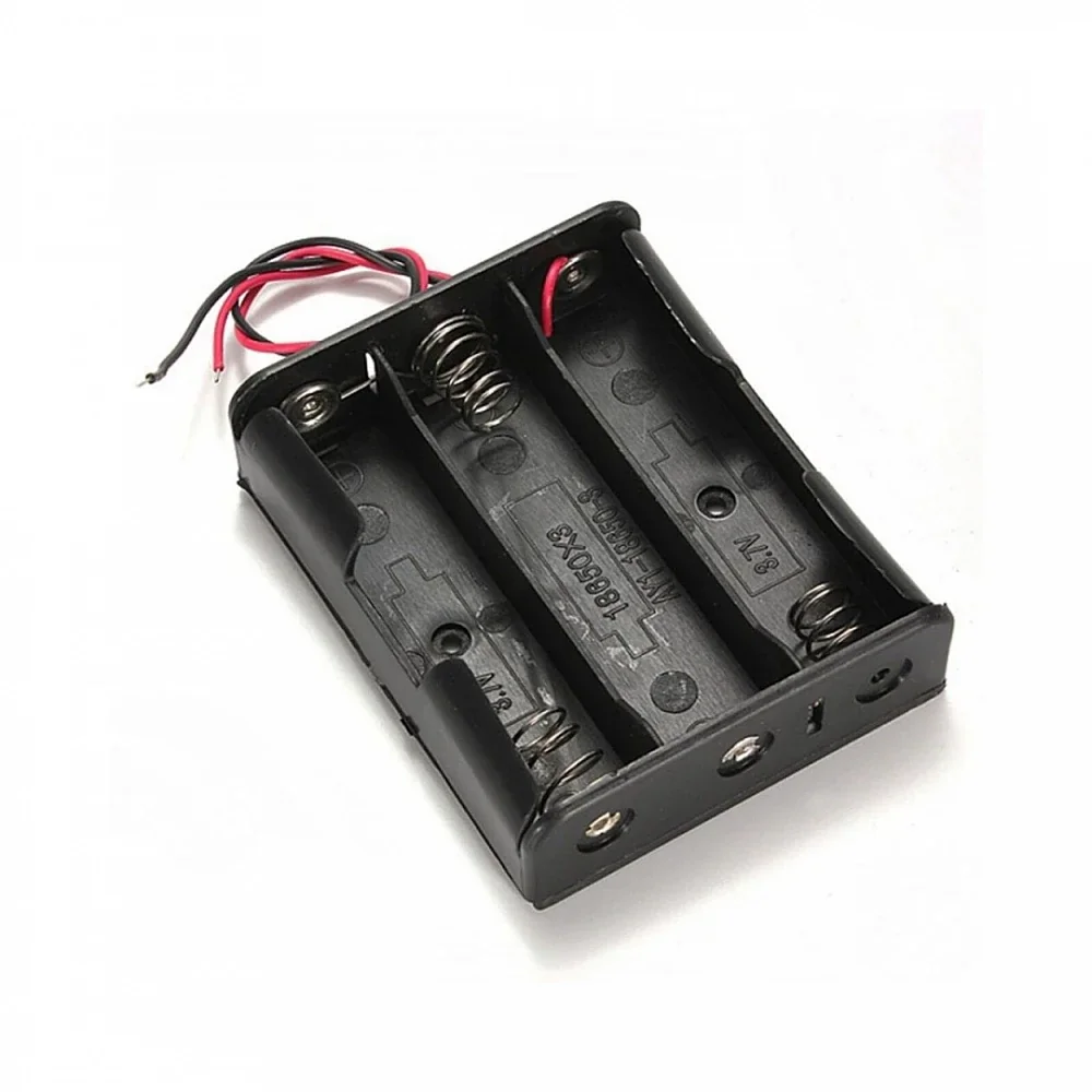
Black Plastic 3×18650 Battery Holder or Case Series Connection With Wire
[Lithium Battery Holder] Black Plastic 3×18650 Battery Holder – Series Connection The Black Plastic 3×18650 Battery Holder is designed to securely hold three 18650 lithium-ion battery cells in series configuration. It provides a convenient and organized way to mount 18650 cells for DIY battery packs, portable electronics, power supplies, LED projects, and other battery-powered applications. The holder is made from durable plastic and features mounting holes for secure installation using suitable screws. It is supplied with red and black connecting wires for convenient connection to an external circuit. ⭐ Key Features Designed for 3 × 18650 battery cells Series connection Black plastic construction Without cover Secure battery positioning Easy installation Built-in mounting holes Red and black connecting wires Suitable for DIY battery pack projects Compact and lightweight design 📋 Technical Specifications Product Type: 18650 Battery Holder Battery Capacity: 3 Cells Battery Type: 18650 Li-Ion Cell Configuration: 3S / Series Connection Nominal Output Voltage: Approximately 11.1V with 3.7V cells Fully Charged Voltage: Approximately 12.6V Material: Plastic Color: Black Cover: Without Cover Connection Wires: Red and Black Mounting: Screw Mount Mounting Holes: Yes Recommended Screw Size: Approximately 3mm Application: Battery Pack / Portable Electronics 🔌 Connection The three 18650 cells are connected in series, increasing the total voltage while maintaining the capacity of a single cell. With standard 3.7V nominal cells, the pack is approximately 11.1V nominal and 12.6V when fully charged. The red wire is the positive connection and the black wire is the negative connection. 🔧 Applications DIY 18650 Battery Packs 3S Lithium-Ion Battery Packs Portable Electronics LED Lighting Projects DIY UPS Projects Arduino Projects ESP8266 / ESP32 Projects Rechargeable Electronics Battery-Powered Devices Electronics Prototyping 📦 Package Includes 1 × 3×18650 Battery Holder / Case – Series Connection, Without Cover ⚠️ Precautions Use only compatible 18650 Li-Ion cells. Use three cells with matching capacity, chemistry, age, and charge condition. Use a suitable 3S BMS/protection and charging circuit. Do not mix damaged or mismatched cells. Check polarity carefully before installation. Do not short-circuit the battery terminals. Do not use damaged, swollen, or leaking cells. Ensure the holder and wiring are securely installed.
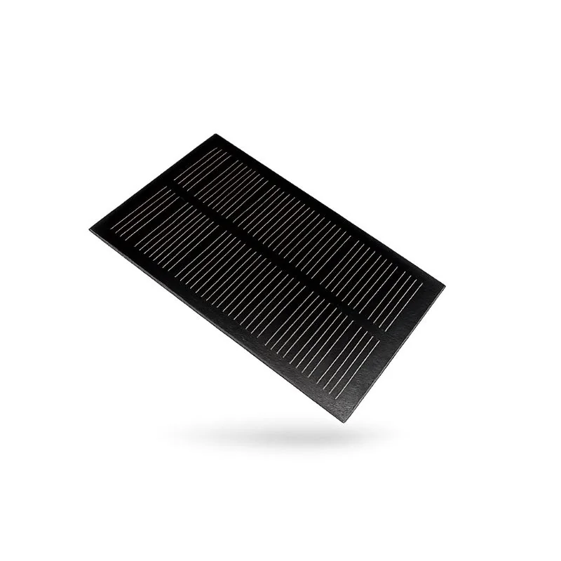
110 × 69mm 5V 180mA Mini Solar Panel Cell Module
[Solar Panel] ☀️ 110 × 69mm 5V 180mA Mini Solar Panel Cell Module (0.9W) 5V Output • 180mA Current • 0.9W Power • Polycrystalline Solar Cell • Compact & Lightweight The 110 × 69mm 5V 180mA Mini Solar Panel Cell Module is a compact and efficient photovoltaic module designed to convert sunlight into clean, renewable electrical energy. Delivering a stable 5V output with a maximum current of 180mA, this solar panel is ideal for powering low-power electronic devices, DIY solar projects, battery charging applications, and educational experiments. Built using high-quality polycrystalline silicon solar cells, the module offers efficient energy conversion while maintaining reliable performance under sunlight. Its lightweight construction and compact dimensions make it easy to integrate into portable devices, robotics projects, solar-powered gadgets, and outdoor applications. Designed for durability, the panel features a weather-resistant construction suitable for outdoor use. With pre-drilled mounting holes, installation is quick and convenient for a wide range of renewable energy projects. ⭐ Features High-efficiency polycrystalline solar panel Stable 5V DC output Maximum output current of 180mA Maximum power output of 0.9W Compact size for portable projects Lightweight and easy to install Weather-resistant construction Pre-drilled mounting holes Suitable for outdoor applications Eco-friendly renewable energy source No external power source required Ideal for educational and DIY projects 📋 Technical Specifications Product Type: Mini Solar Panel Cell Module Cell Type: Polycrystalline Silicon Maximum Power Output: 0.9W Output Voltage: 5V DC Maximum Output Current: 180mA Panel Dimensions: 110 × 69 mm Operating Temperature: -40°C to +85°C Storage Temperature: -40°C to +85°C Construction: Weather-Resistant Connector: None (Solder Wire Connection) Weight: Approximately 15g 🔧 Applications Suitable for: DIY Solar Projects Solar Battery Chargers Mobile Phone Charging Projects Arduino Projects ESP32 & ESP8266 Projects Raspberry Pi Accessories Robotics Projects Solar Garden Lights Educational Science Experiments IoT Devices Portable Electronic Devices Renewable Energy Demonstrations Emergency Backup Power Projects Small DC Loads 📦 Package Includes 1 × 110 × 69mm 5V 180mA Mini Solar Panel Cell Module ⚠️ Note Output voltage and current depend on sunlight intensity and panel orientation. For battery charging applications, use a suitable solar charge controller or charging module. This panel is intended for low-power applications and may not provide sufficient power under low-light conditions. Product appearance may vary slightly depending on the manufacturing batch.
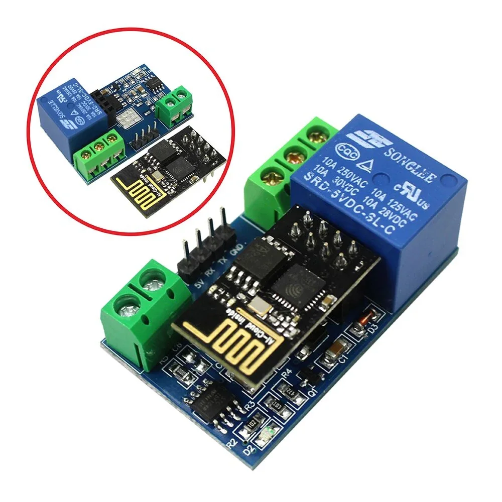
ESP8266 WiFi 5V 1 Channel Relay Module Good Quality
[Relay Module] General Info : Onboard ESP8266 WIFI module, AP mode can be connected at the same time 5 client The module has two ways to work: (i) mobile phone directly mounted on the WIFI module; (ii) mobile phone and WIFI module also carried on the router. How to use : Onboard ESP8266 WIFI module has three operating modes: STA (client), AP (hot), STA + AP (client + hot), according to the work of the module to select the corresponding WIFI module mode of operation The The module needs to use the serial debugging software on the computer and USB to TTL module to send AT commands to configure the WIFI module, USB to TTL module RX, TX, GND pin, then the module on the TX, RX, GND pin, IN +, IN – 5V power supply. Usage Instructions 1) Hardware Connection: Insert the pre-programmed ESP-01/01S module into the onboard 2×4 pin female header (as shown in the diagram below). 2) Power Supply : Connect a DC 5V-12V power source to the module, with the positive terminal to VCC and the negative terminal to GND. 3) Mobile WiFi Connection : Open your phone's WLAN settings, search for and connect to the ESP8266-XXXX hotspot (default password: 12345678). 4) Launch Control APP : Run the pre-installed ESP8266 Controller application on your Android phone. 5) Configure IP Address : Enter the default IP address: 192.168.1.1 in the APP to remotely control the relay switch via your phone. Transmission distance: Open environment, the mobile phone mounted on the WIFI module when the maximum transmission distance of 400m. When the WiFI module and mobile phone at the same time carried on the router when the transmission distance according to the router’s signal weakly; Board function description : IN +, IN-: 5V power input; TX, RX, GND: Serial debug pin; Onboard the ESP8266 WIFI module has three work modes: STA (client), AP (hot), the STA + Ap( hot +client), according to the workings of a module to the corresponding choice of WIFI module working mode. Module need before use serial debugging software and USB to TTL module send serial command was carried out on the WIFI module configuration (don’t power outages after configuration is complete, as some of the parameters of WIFI module cannot be saved when the power is cut off), mobile phone and WIFI module after establishing a network connection can use the phone APP control relay. Control Commands : When cell phone equipped with WiFi module sends commands in the following order: (The default baud rate 115200) AT+CWMODE=2, namely AP mode is selected. AT+RST, reset. AT+CIPMUX=1, open multiple connections. AT+CIPSERVER=1,8080, configure the TCP server, set the port. AT+CIOBAUD=9600 set the baud rate to 9600. (working in relays to control the baud rate 9600). AT+CIFSR to view the AP mode IP address, such as the APIP, “192.168.4.1”. Cell phone WIFI signal connection name starts with AI-THINKER or ESP8266. In the “TCP connection” address and port into the APP, such as 192.168.4.1 and 8080. Click on the grey box relays can be controlled. Features: Onboard Module: ESP8266 wifi module; in AP mode it can connect with 5 Clients at the same time Operating Way: cellphone carried on wifi module; cellphone and wifi module carried on the same router, and use the APP to control relay Diode effusion protection. Short response time
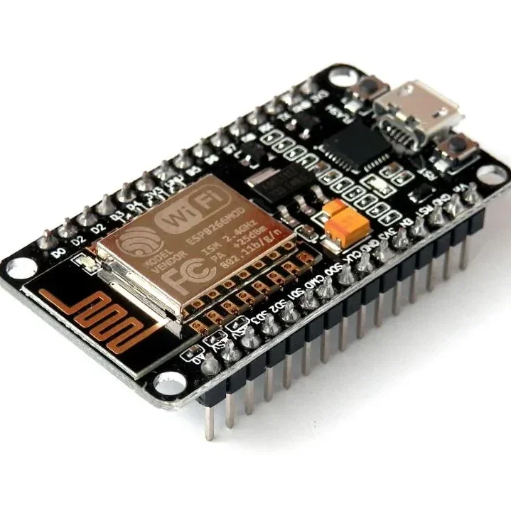
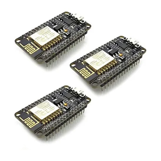
ESP8266 NodeMCU CP2102 ESP-12E WiFi Development Board
[ESP Modules] ESP8266 NodeMCU CP2102 ESP-12E WiFi Development Board ESP8266 ESP-12E • CP2102 USB Interface • Built-in WiFi • Arduino & Lua Compatible • IoT Development Board The ESP8266 NodeMCU CP2102 ESP-12E WiFi Development Board is a compact and powerful development board designed for IoT (Internet of Things), wireless communication, home automation, robotics, and embedded system projects. Based on the highly popular ESP8266 ESP-12E WiFi module, it combines a 32-bit microcontroller, WiFi connectivity, and a CP2102 USB-to-Serial interface on a single breadboard-friendly board. The board comes preloaded with NodeMCU firmware, allowing easy programming using Lua scripting, while also offering full compatibility with the Arduino IDE, making it suitable for both beginners and advanced developers. With integrated 802.11 b/g/n WiFi, TCP/IP networking, multiple GPIO pins, PWM, I2C, SPI, and UART interfaces, it provides everything required for rapid IoT prototyping and wireless application development. The onboard CP2102 USB interface, 3.3V voltage regulator, and logic-level conversion circuitry allow direct connection to a computer for programming and power, eliminating the need for external USB-to-Serial converters. ⭐ Features ESP8266 ESP-12E WiFi module Built-in CP2102 USB-to-Serial interface 802.11 b/g/n WiFi connectivity Integrated TCP/IP protocol stack 32-bit processor with onboard memory Compatible with Arduino IDE, Lua, and NodeMCU firmware Breadboard-friendly compact design Multiple GPIO pins Supports PWM, I2C, SPI, and UART Onboard 3.3V voltage regulator Logic-level conversion circuitry included Low power consumption Ideal for IoT and wireless projects Easy plug-and-play programming 📋 Technical Specifications Product Type: WiFi Development Board Model: ESP8266 NodeMCU ESP-12E Microcontroller: ESP8266EX WiFi Standard: IEEE 802.11 b/g/n USB Interface: CP2102 Operating Voltage: 3.3V Input Voltage: 5V via Micro USB Flash Memory: 4MB CPU: 32-bit Tensilica L106 Clock Frequency: 80MHz / 160MHz GPIO Pins: Multiple Digital I/O Communication Interfaces: UART, SPI, I2C PWM Support: Yes ADC: 1 Channel (10-bit) USB Connector: Micro USB Firmware: NodeMCU (Preloaded) Programming Support: Arduino IDE, Lua, ESP8266 SDK Board Size: Approx. 58 × 31 mm 🔧 Applications IoT (Internet of Things) Projects Home Automation Smart Lighting Systems WiFi Sensor Nodes Wireless Data Logging Robotics Projects Arduino WiFi Projects ESP8266 Development Remote Monitoring Systems MQTT Applications Web Server Projects Smart Agriculture Industrial Automation DIY Electronics Educational Projects 📦 Package Includes 1 × ESP8266 NodeMCU CP2102 ESP-12E WiFi Development Board ⚠️ Note Operates at 3.3V logic levels. Install the CP2102 USB driver if the board is not detected by your computer. Use a good quality Micro USB cable for programming and power. Product appearance may vary slightly depending on the manufacturing batch.
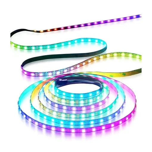
WS2812B 1M 60LED DC 5V Addressable LED Strip Roll Non Waterproof 1 Meter
[RGB LED Strip] ✨ WS2812B 60 LED/m Addressable LED Strip (1 Meter, 5V) – High Brightness, DIY RGB Lighting Upgrade your lighting projects with the WS2812B 60 LED/m Addressable RGB LED Strip — the most popular choice for creators, hobbyists, and professionals. Designed with individually addressable RGB LEDs, this 1-meter strip lets you create stunning animation effects, rainbow patterns, breathing lights, chases, waves, and more using any compatible microcontroller. Powered by a stable 5V input, this LED strip delivers bright, vibrant colors with seamless gradients and superior consistency. Perfect for Arduino, ESP32, Raspberry Pi, PC mods, gaming setups, TV backlights, decorative lighting, DIY electronics, and smart home projects. ⭐ Key Features Individually Addressable LEDs (WS2812B IC)Each of the 60 LEDs per meter can be controlled separately for advanced lighting effects. High Brightness & True RGB ColorsProduces vivid and smooth color transitions with 256-level brightness control. Easy 5V Power InputWorks with USB, power banks, Arduino 5V output, and 5V adapters. Flexible & Cuttable StripCut between every LED and solder easily for custom length. Compatible With Popular PlatformsWorks with Arduino, ESP8266, ESP32, Raspberry Pi, FastLED, WLED, NeoPixel libraries. Non-Waterproof (Indoor Use)Ideal for desks, PCs, shelves, room décor, and electronic builds. 🔧 Technical Specifications Model: WS2812B Addressable RGB LED Strip Length: 1 Meter LED Density: 60 LEDs per meter Voltage: DC 5V Power Consumption: ~18W per meter (full white) Control Signal: Single-wire digital (Din) Type: Non-Waterproof LED Package: 5050 RGB Beam Angle: 120° 🎯 Ideal Applications DIY RGB lighting projects Gaming room & PC case mods TV/monitor ambient backlight Arduino & ESP projects Festivals, decoration & ambient lighting Robotics & wearables Smart home LED animations
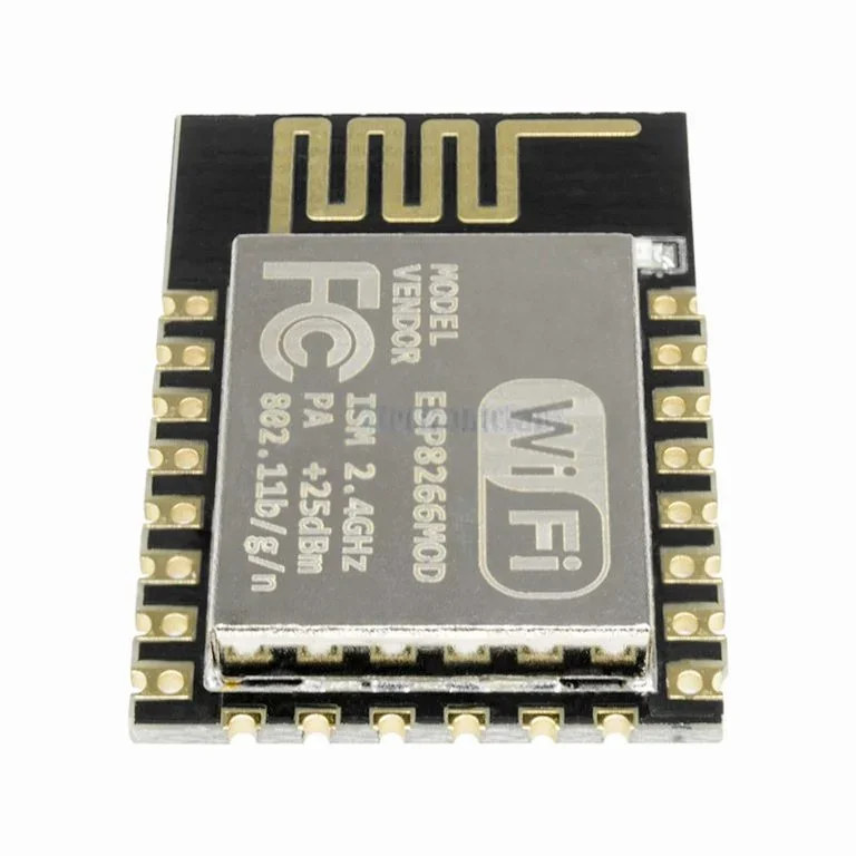 Out of stock
ESP-12E: ESP8266 Serial Port WIFI Wireless Transceiver Module For Arduino
[ESP Modules] This is ESP-12E: ESP8266 Serial Port WIFI Wireless Transceiver Module For Arduino. This small WIFI transceiver is the perfect solution for home Automation and IoT applications. It can be the replacement of your NRF24L01, it can talk to your WIFI router directly through the UART MCU’s (Rx, Tx). The ESP-12 module is one of the most complete of the ESP family as it allows you to use the biggest amount of pins of all of them. You can program this module to work stand alone with the Arduino IDE or with LUA as NodeMCU. The system is equipped with ESP8266 manifested leading features are: energy saving VoIP quickly switch between the sleep/wake patterns, with low-power operation adaptive radio bias, front-end signal processing functions. The ESP8266-03 is one of the smallest versions of this module. It includes a built-in ceramic antenna. Features : WS2812 Led on board. 802.11 b/g/n Wi-Fi Direct (P2P), soft-AP Integrated TCP/IP protocol stack Integrated TR switch, balun, LNA, power amplifier and matching network Integrated PLL, regulators, DCXO and power management units +19.5dBm output power in 802.11b mode Power down leakage current of <10uA Integrated low power 32-bit CPU could be used as an application processor SDIO 1.1 / 2.0, SPI, UART STBC, 1×1 MIMO, 2×1 MIMO A-MPDU & A-MSDU aggregation & 0.4ms guard interval Wake up and transmit packets in < 2ms Standby power consumption of < 1.0mW (DTIM3) Access Point and Station Modes. Package Includes : 1 x ESP-12E: ESP8266 Serial Port WIFI Wireless Transceiver Module For Arduino
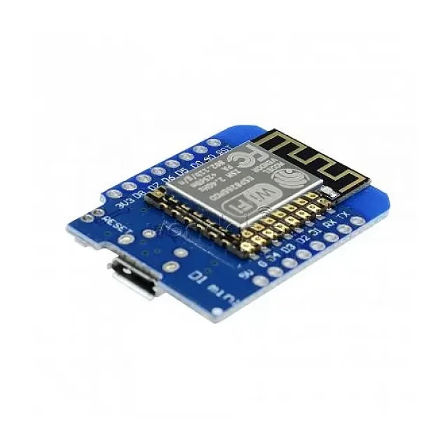
ESP8266 D1 Mini V2 NodeMcu Lua WIFI IOT Development Board
[ESP Modules] D1 Mini V2 NodeMcu Lua WIFI IOT Development Board is a mini WIFI board based on ESP-8266EX. 11 digital input/output pins, all pins have interrupt/PWM/I2C/one-wire supported(except D0) 1 analog input(3.3V max input) and a Micro USB connection. The development board features WiFi-SoC ESP8266 and is made for fast Internet-of-Things (IoT) prototyping. It is flashed with the latest firmware version and can be set up and programmed right away with the onboard micro USB connection. With only a few lines of code, the NodeMCU Dev Kit connects to your local network and ready for control by other network members like computers and smartphones. The d1 mini is an ESP8266 development board that is compact, versatile, and very easy to use with the Arduino IDE. It supports natively by the Expressive SDK. Features : Use BRT (Bias Resistor Transistor) Easier into flash mode. 30% increase in radiating area Good stability. On-Board Switching Power Supply Specifications: Microcontroller ESP-8266EX Flash Memory 4MB Digital I/O Pins 11 (all I/O pins have interrupt/PWM/I2C/one-wire capability, except for D0) Analog Input Pins 1 (3.2V max input) Operating Voltage 3.3V Output 5V Compatible with Arduino, NodeMCU, and MicroPython Package Includes : 1 x D1 Mini V2 NodeMcu Lua WIFI IOT Development Board 2 x Long female pin 2 x Short female pin 2 x Normal pin
 Out of stock
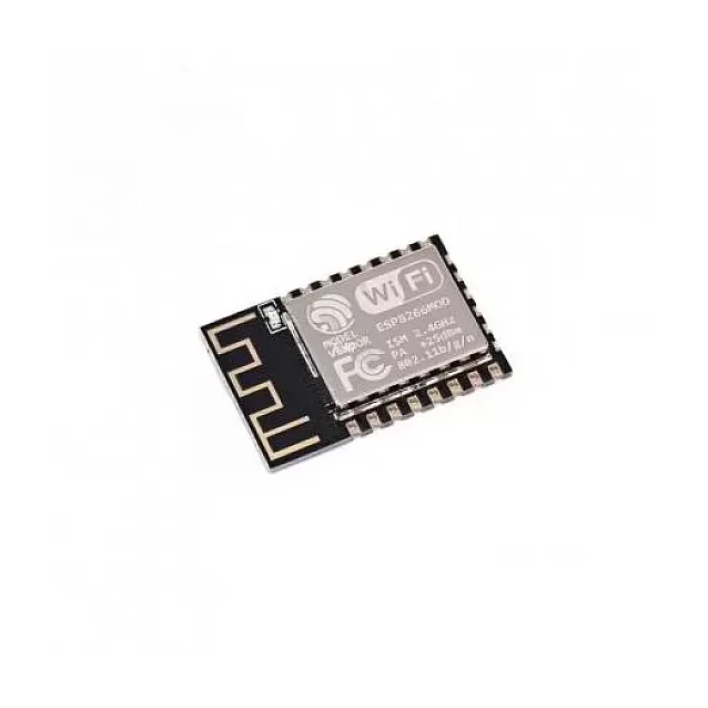
ESP-12F ESP8266 Wifi Wireless IoT Board Module
[ESP Modules] The ESP-12F ESP8266 WiFi Module is a powerful and low-cost WiFi transceiver module designed for Internet of Things (IoT) applications. Built around the ESP8266 SoC, this module integrates a full TCP/IP protocol stack, enabling microcontrollers to connect directly to WiFi networks. With its integrated 32-bit RISC processor, on-chip memory, and multiple communication interfaces, the ESP-12F module can either host an application independently or act as a WiFi adapter for another microcontroller such as Arduino, Raspberry Pi, or STM32. Each module is typically shipped with AT command firmware, allowing easy communication through UART serial interface. This means developers can quickly add WiFi functionality to existing hardware without complex programming. The ESP-12F version improves performance compared to earlier modules by offering: Stronger WiFi signal output Improved anti-interference capability Optimized PCB antenna design Better impedance matching The module supports station mode, soft-AP mode, and combined AP + station mode, making it highly versatile for IoT networking. Because of its high integration, small size, and low power consumption, the ESP-12F module is widely used in: IoT devices Home automation systems Smart appliances Wireless sensor networks Industrial monitoring systems ⭐ Key Features Based on ESP8266 SoC Built-in TCP/IP protocol stack Integrated 2.4GHz WiFi Supports Station / SoftAP / Station + AP modes Pre-programmed AT command firmware Compact SMD design Strong PCB antenna Low power consumption Multiple communication interfaces 🔧 Technical Specifications Model: ESP-12F Chipset: ESP8266 WiFi Standard: IEEE 802.11 b/g/n Frequency: 2.4 GHz Operating Voltage: 3.3V Maximum Current: ~240mA Standby Power: < 1mW Interface: UART / SPI / SDIO Baud Rate: 115200 (default) Communication Format: 8N1 Security: WPA / WPA2 Package Type: 32-Pin QFN Output Power: +19.5 dBm 📡 Supported Interfaces UART SPI SDIO 1.1 / 2.0 I2S (audio interface) Multiple GPIO pins 🎯 Applications IoT projects Smart home automation Wireless sensor networks Arduino WiFi connectivity Remote monitoring systems Industrial IoT applications 📦 Package Includes 1 × ESP-12F ESP8266 WiFi Module
 Out of stock
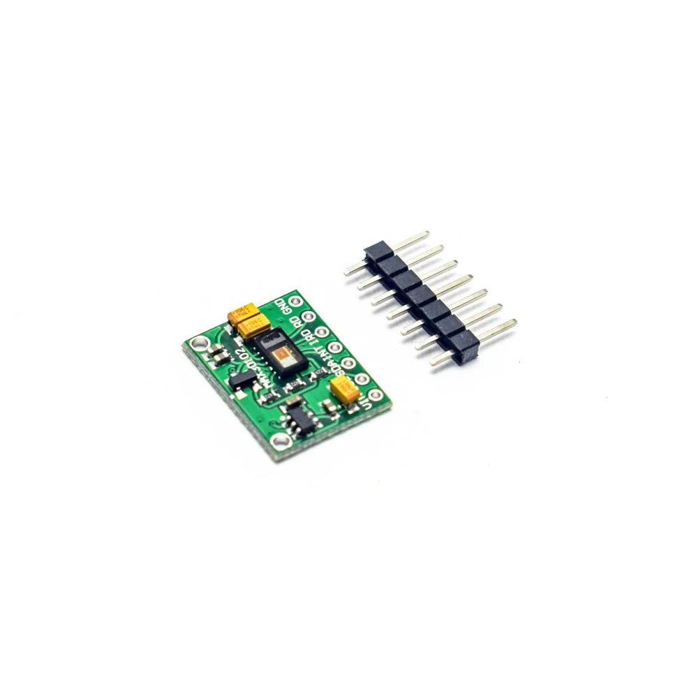
MAX30102 Pulse Oximeter Heart Rate Sensor Module
[Proximity Sensor] MAX30102 is a sensor that combines a pulse oximeter and a heart rate monitor. It’s an optical sensor that measures the absorbance of pulsating blood through a photodetector after emitting two wavelengths of light from two LEDs – a red and an infrared one. This particular LED colour combination is designed to allow data to be read with the tip of one’s finger. It is fully configurable through software registers and the digital output data is stored in a 16-deep FIFO within the device. It has an I2C digital interface to communicate with a host microcontroller. The pulse oximetry subsystem in MAX30102 consists of ambient light cancellation (ALC), 16-bit sigma-delta ADC, and a proprietary discrete-time filter. It has an ultra-low-power operation which makes it ideal for battery-operated systems. MAX30100 operates on a supply in the range of 1.8 to 3.3V. It can be used in wearable devices, fitness assistant devices, medical monitoring devices, etc. This sensor works on 3.3V Devices directly. You can connect it to 3.3V devices like ESP8266, ESP32, etc. directly. To use it with the Arduino UNO, Mega, Nano, etc. use a level shifter in between. Else I2C connection will not work. Features Heart-Rate Monitor and Pulse Oximeter Sensor in LED Reflective Solution Tiny 5.6mm x 3.3mm x 1.55mm 14-Pin Optical Module Integrated Cover Glass for Optimal, Robust Performance Ultra-Low Power Operation for Mobile Devices Programmable Sample Rate and LED Current for Power Savings Low-Power Heart-Rate Monitor (< 1mW) Ultra-Low Shutdown Current (0.7µA) Fast Data Output Capability High Sample Rates Robust Motion Artifact Resilience High SNR -40°C to +85°C Operating Temperature Range
 Out of stock
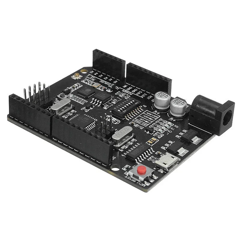
Uno+WiFi R3 AtMega328p+NodeMSU ESP8266 Compatible for Arduino UNO
[Arduino Boards] Arduino UNO WIFI ESP8266 CH340 Development Board Uno+WiFi R3 AtMega328p+NodeMSU ESP8266 8MB Memory USB-TTL CH340G Compatible for Arduino UNO is full integration on one board: Uno R3 ATmega 328 and WiFi ESP8266 with memory 8Mb (MegaByte). All of the modules can work together or separately. And everyone has their own pinout headers. The convenient solution for the development of new projects requiring Uno and WiFi. Via USB you can update sketches and firmware for ATmega328 and for ESP8266. For this onboard have the USB-serial converter CH340G. It is a modernized version of the classic Arduino UNO R3 board. Full integration of a microcontroller ATmega328 and a Wi-Fi chip ESP8266 with 8 MB memory on one board. All modules can work together or individually. Each of the microcontrollers has led to connecting peripheral sensors and modules. A convenient solution for developing new projects that require Wi-Fi. Through USB, you can update sketches and firmware for both ATmega328 and ESP8266. For this on board, there is a UART converter CH340G. The board has a DIP switch, which switches the modes of interaction of microcontrollers ATmegaa328 and esp8266. The operations of this board are very simple. The board has a DIP switch, to connect the modules. For example, USB and ATmega328, USB and ESP8266, ATmega328 and ESP8266. Table DIP- switch: Connection DIP 1 2 3 4 5 6 7 ATmega328<->ESP8266 ON ON OFF OFF OFF OFF OFF USB <->ATmega328 OFF OFF ON ON OFF OFF OFF USB<->ESP8266 (Update firmware or sketch) OFF OFF OFF OFF ON ON ON USB<->ESP8266 (communication) OFF OFF OFF OFF ON ON OFF All independent OFF OFF OFF OFF OFF OFF OFF Features: USB-TTL converter. USB5V (500mA max.)Power IN. Logic Level: 5V. Operating Supply Voltage: 5V. Digital I/O Pins: 14. Analog I/O Pins: 6. Interface Type: serial. Operating temperature: −40С°/+125С°. Specifications: Microcontroller ATmega328IC Wi-Fi Module ESP8266 Input supply voltage (V) 3.3 ~ 5 Current consumption (mA) 800 USB to serial converter CH340G VIN/DC Jack (V) 9 ~ 24 WiFi 802.11 b/g/n 2.4 GHz USB type Micro USB USB Clock Frequency (MHz) 16 Memory Size (MB) 8 Package Includes: 1 x Uno+WiFi R3 AtMega328p+NodeMSU ESP8266 Compatible for Arduino UNO
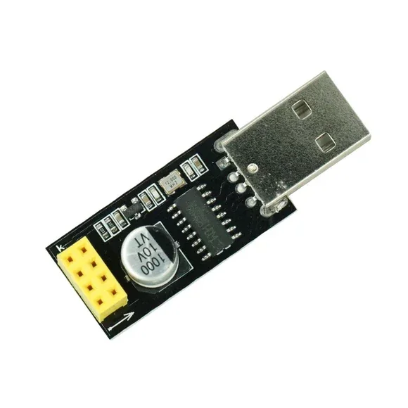
USB to UART/ESP8266 Adapter Programmer for ESP-01 Wi-Fi Modules with CH340G Chip
[Development Board, ESP Modules] ESP8266 Adapter Programmer / USB TO UART Converter for ESP8266 This USB to UART/ESP8266 Adapter Programmer for ESP-01 WiFi Modules with CH340G Chip converts the signal from a USB interface to a PC / laptop to match a serial module ESP8266. This converter module has a CH340 chip which is reliable and with high performance. It is compatible with most Windows systems. The adapter features integrated capacitors to maintain a current of 1000 μF. USB to ESP-01 adapter module has CH340G USB to TTL driver IC onboard, so you can easily use your computer to do ESP-01 functional debugging. ESP-01 serial wifi module can be directly plugged into the yellow pin header without any connecting wire. USB to UART/ESP8266 Programmer used for an ESP-01 module with the ESP8266 chip. It has CH340G USB to TTL driver IC onboard, so you can easily use your computer to do with ESP-01. Features : Using CH340 turns serial port chip for stable performance and compatibility. Supports all basic windows versions. The adapter plate integrated 1000μF solid capacitors to ensure the current supply The power supply will not be a problem to make the WIFI module crashes unresponsive. Using a 3225 SMD crystal oscillator, improves the stability of serial work, on a beautiful and tall. The interposer board is specifically designed for ESP8266 The USB Turn serial port. Package Includes : 1 x USB to UART/ESP8266 Adapter Programmer for ESP-01 Wi-Fi Modules with CH340G Chip ESP8266 Wifi Modules
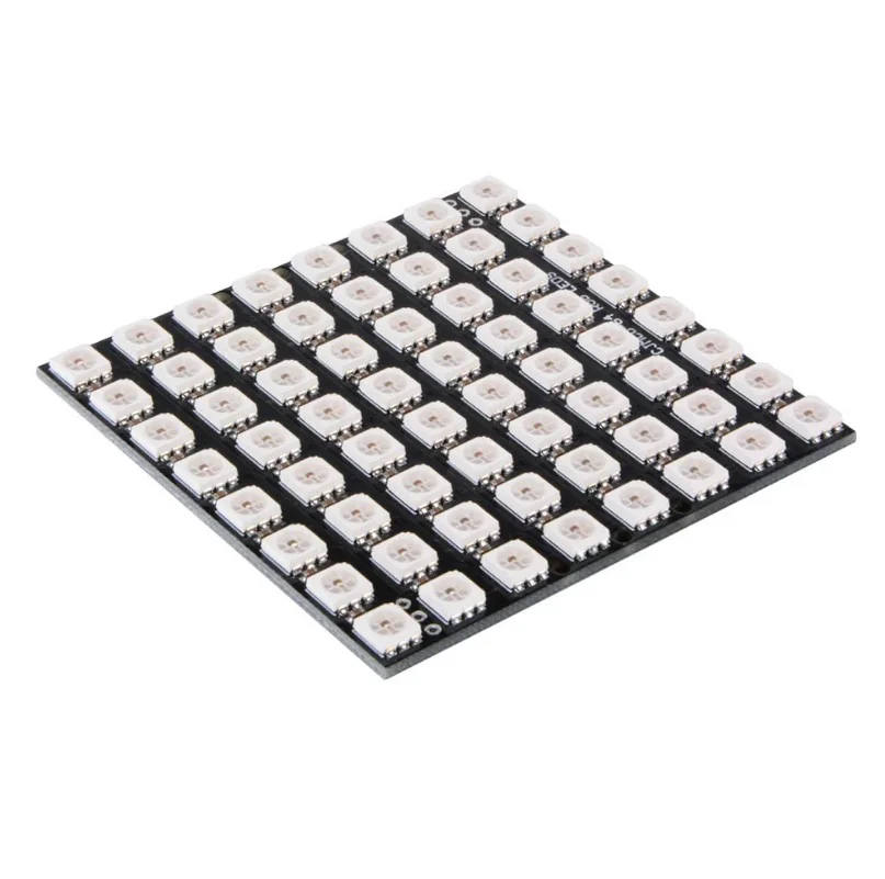
CJMCU 64 Bit 8×8 RGB WS2812 LED Driver Development Board
[LED/LCD Display Module] Product Description The CJMCU 64-Bit 8×8 RGB WS2812 LED Driver Development Board is a compact, high-performance LED matrix designed for makers, hobbyists, and developers. Featuring 64 individually addressable RGB LEDs (WS2812B) arranged in an 8×8 grid, this module lets you create stunning light patterns, animations, and color effects with ease. Each LED integrates a built-in driver IC, allowing precise control over brightness and color through a single data line. Compatible with popular microcontrollers such as Arduino, ESP32, and Raspberry Pi, this board is perfect for DIY projects, display systems, lighting effects, and visual art installations. Its 5V input and chainable design make it easy to connect multiple boards for larger displays. Compact, efficient, and versatile — the CJMCU 8×8 WS2812 RGB board brings your lighting ideas to life. Features 💡 64 Individually Addressable LEDs: Control each LED independently to create custom animations and effects. 🔌 Easy to Interface: Works seamlessly with Arduino, ESP8266, ESP32, Raspberry Pi, and other controllers. 🌈 Vibrant RGB Colors: Delivers full 24-bit color with smooth transitions and vivid brightness. 🔄 Chainable Design: Connect multiple boards for extended LED matrix displays. ⚙️ Built-in Driver IC (WS2812B): Simplifies wiring and control using a single data pin. 🧩 Compact 8×8 Grid: Ideal for DIY projects, wearable tech, and artistic LED installations. 🔋 5V Operating Voltage: Compatible with USB power and regulated 5V supplies. Specifications Specification Details Model CJMCU 64-Bit 8×8 RGB LED Board LED Type WS2812B LED Count 64 LEDs (8×8 grid) Operating Voltage 5V DC Communication Single-wire serial interface Color RGB (24-bit) Compatibility Arduino, ESP32, Raspberry Pi, and others Dimensions Compact 8×8 layout Mounting PCB with solder pads for chaining Package Includes : 1 x CJMCU 64 Bit 8×8 RGB LED WS2812 Driver Development Board.
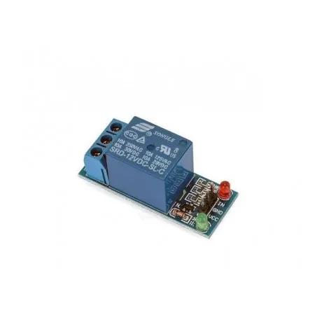
1 Channel 12V Relay Module without Optocoupler
[Relay Module] 🔌 12V 1 Channel 7A Relay Module for Arduino, Raspberry Pi & Microcontrollers 12V Trigger • 7A Relay • Compact Design • Ideal for Automation & DIY Projects The 12V 1 Channel 7A Relay Module is a compact and reliable relay board designed to control AC and DC loads using low-voltage control signals from microcontrollers and development boards. Operating on a 12V DC trigger voltage, it can be directly interfaced with Arduino, Raspberry Pi, ESP32, ESP8266, AVR, PIC, 8051, ARM, and other embedded systems. The module is equipped with a high-quality 7A electromagnetic relay capable of switching 250V AC or 30V DC loads. It features LED indicators for power and relay status, making debugging and operation simple. Standard header pins allow easy connection to development boards, while screw terminals provide secure wiring for external loads. This relay module is ideal for home automation, industrial control, IoT projects, robotics, lighting control, motor switching, and various DIY electronics applications. ⭐ Features Single-channel 12V relay module High-quality 7A electromagnetic relay Compatible with Arduino, Raspberry Pi, ESP32, AVR, PIC, ARM and more 12V DC trigger input LED power and relay status indicators Standard header pin interface Screw terminal output connections Compact PCB design Reliable and stable operation Easy installation 📋 Technical Specifications Product Type: Relay Module Relay Channels: 1 Operating Voltage: 12V DC Trigger Voltage: 12V DC Trigger Current: Approx. 20mA Maximum Switching Voltage (AC): 250V AC Maximum Switching Current (AC): 7A Maximum Switching Voltage (DC): 30V DC Maximum Switching Current (DC): 7A Relay Contact Type: SPDT (NO / NC / COM) Connection Type: Screw Terminal + Header Pins Operating Temperature: -40°C to +85°C Board Dimensions: Approx. 48 × 29 × 17 mm (May vary slightly by manufacturer) Weight: Approx. 15g 🔧 Applications Suitable for: Arduino Projects Raspberry Pi Projects ESP32 & ESP8266 Projects Home Automation Industrial Automation Smart Switches Lighting Control Fan Control Pump Control Small Motor Switching Security Systems Robotics IoT Projects DIY Electronics 📦 Package Includes 1 × 12V 1 Channel 7A Relay Module ⚠️ Note This module is intended for switching high-voltage AC/DC loads. Always disconnect power before wiring. Product images are for illustrative purposes only. The actual product may vary slightly depending on the manufacturing batch.
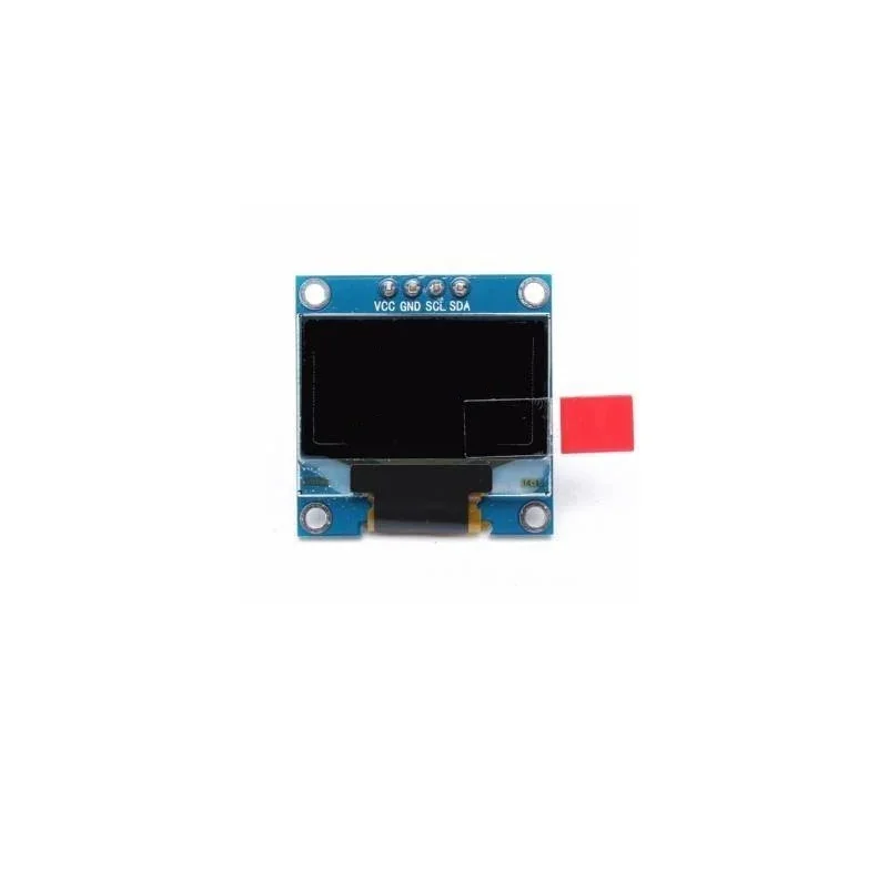
0.96 Inch I2C/IIC 128×64 OLED Display Module Blue (4 Pin)
[LED/LCD Display Module] The 0.96 Inch I2C/IIC OLED Display Module (128×64) is a compact and efficient display designed for microcontroller and embedded system applications. Based on OLED (Organic Light-Emitting Diode) technology, the display provides bright blue pixels with excellent contrast and wide viewing angles. Unlike traditional LCD displays, OLED displays are self-emitting, meaning they do not require a backlight. This results in lower power consumption, higher brightness, and better contrast, making OLED displays ideal for portable electronics and embedded systems. The module uses the popular SSD1306 driver controller, allowing easy integration with development platforms such as Arduino, ESP8266, ESP32, Raspberry Pi, STM32 and other microcontrollers. With its I2C/IIC communication interface, the display requires only 4 pins (VCC, GND, SCL, SDA), saving valuable GPIO pins on your microcontroller. It supports widely available libraries such as Adafruit SSD1306 and U8g2, making it simple to display text, graphics, icons, and sensor data. Thanks to its high brightness, ultra-thin design, wide operating temperature range, and low power consumption, the 0.96″ OLED display module is widely used in IoT devices, robotics, wearable electronics, sensor monitoring systems, and DIY electronics projects. ⭐ Key Features 0.96 inch OLED display module 128 × 64 pixel resolution Blue monochrome display SSD1306 display controller I2C / IIC communication interface Requires only 4 connection pins High brightness and high contrast Wide viewing angle Low power consumption Compatible with Arduino, ESP32, NodeMCU, Raspberry Pi 🔧 Technical Specifications Display Size: 0.96 inch Resolution: 128 × 64 pixels Display Type: OLED (Organic Light Emitting Diode) Display Color: Blue Controller Chip: SSD1306 Interface Type: I2C / IIC Working Voltage: 3.3V – 5V Communication Pins: VCC, GND, SCL, SDA Driver Support: Arduino / Raspberry Pi libraries 📌 Interface Pin Configuration Pin Function VCC 3.3V – 5V Power Supply GND Ground SCL Serial Clock SDA Serial Data 🎯 Applications Arduino projects ESP32 / ESP8266 IoT devices Sensor data display Robotics systems Battery monitors Weather stations DIY electronics projects 📦 Package Includes 1 × 0.96 Inch I2C/IIC 128×64 OLED Display Module Blue (4 Pin)
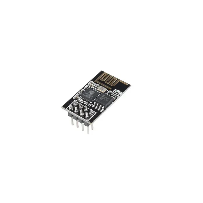
ESP-01 ESP8266 Serial WIFI Wireless Transceiver Module
[ESP Modules] The ESP 01 ESP8266 Serial WIFI Wireless Transceiver Module is a self-contained SOC with integrated TCP/IP protocol stack that can give any microcontroller access to your WiFi network. The ESP8266 is capable of either hosting an application or offloading all Wi-Fi networking functions from another application processor. Each ESP8266 module comes pre-programmed with an AT command set firmware, meaning, you can simply hook this up to your Arduino device and get about as much WiFi-ability as a WiFi Shield offers (and that’s just out of the box)! The ESP8266 module is an extremely cost-effective board with a huge, and ever-growing, community. This module has a powerful enough on-board processing and storage capability that allows it to be integrated with the sensors and other application-specific devices through its GPIOs with minimal development up-front and minimal loading during runtime. Its high degree of on-chip integration allows for minimal external circuitry, including the front-end module, which is designed to occupy minimal PCB area. The ESP8266 supports APSD for VoIP applications and Bluetooth co-existence interfaces, it contains a self-calibrated RF allowing it to work under all operating conditions and requires no external RF parts. There is an almost limitless fountain of information available for the ESP8266, all of which has been provided by amazing community support. In the useful links section below you will find many resources to aid you in using the ESP8266, even instructions on how to transforming this module into an IoT (Internet of Things) solution! Note: The ESP8266 Module is not capable of 5-3V logic shifting and will require an external Logic Level Converter. Please do not power it directly from your 5V dev board. This new version of the ESP8266 WiFi Module has increased the flash disk size from 512k to 1MB. Features : Wi-Fi Direct (P2P), soft-AP Integrated TCP/IP protocol stack It features an integrated TR switch, balun, LNA, power amplifier and matching network Equips integrated PLL, regulators, DCXO and power management units Integrated low power 32-bit CPU could be used as an application processor SDIO 1.1 / 2.0, SPI, UART STBC, 1×1 MIMO, 2×1 MIMO A-MPDU & A-MSDU aggregation & 0.4ms guard interval Wake up and transmit packets in < 2ms Standby power consumption of < 1.0mW (DTIM3) Package Includes : 1 x ESP-01 ESP8266 Serial WIFI Wireless Transceiver Module