
All products · 50 of 1440
Electronics, sensors, robotics kits, PC components, peripherals — everything Unik Systems carries, in one place.
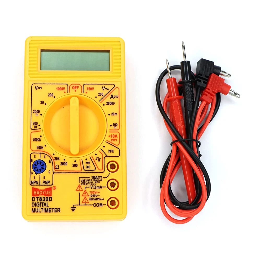
Digital Multimeter
7 functions, 19 ranges. DC voltage 200mV–1kV, AC voltage 200–750V, DC current 200µA–10A, resistance 200–2MΩ, transistor & diode test.
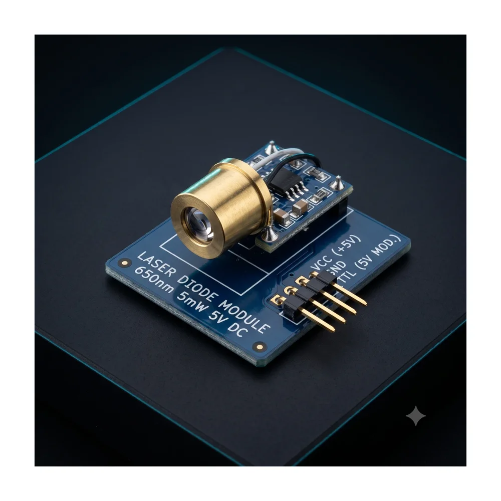
Laser Diode Module (650nm 5mW)
650nm 6mm 5V DC 5mW mini laser dot diode module.
 Out of stock
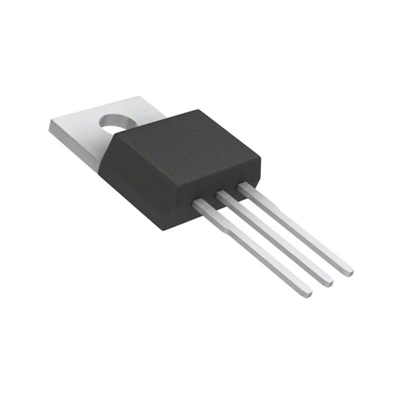
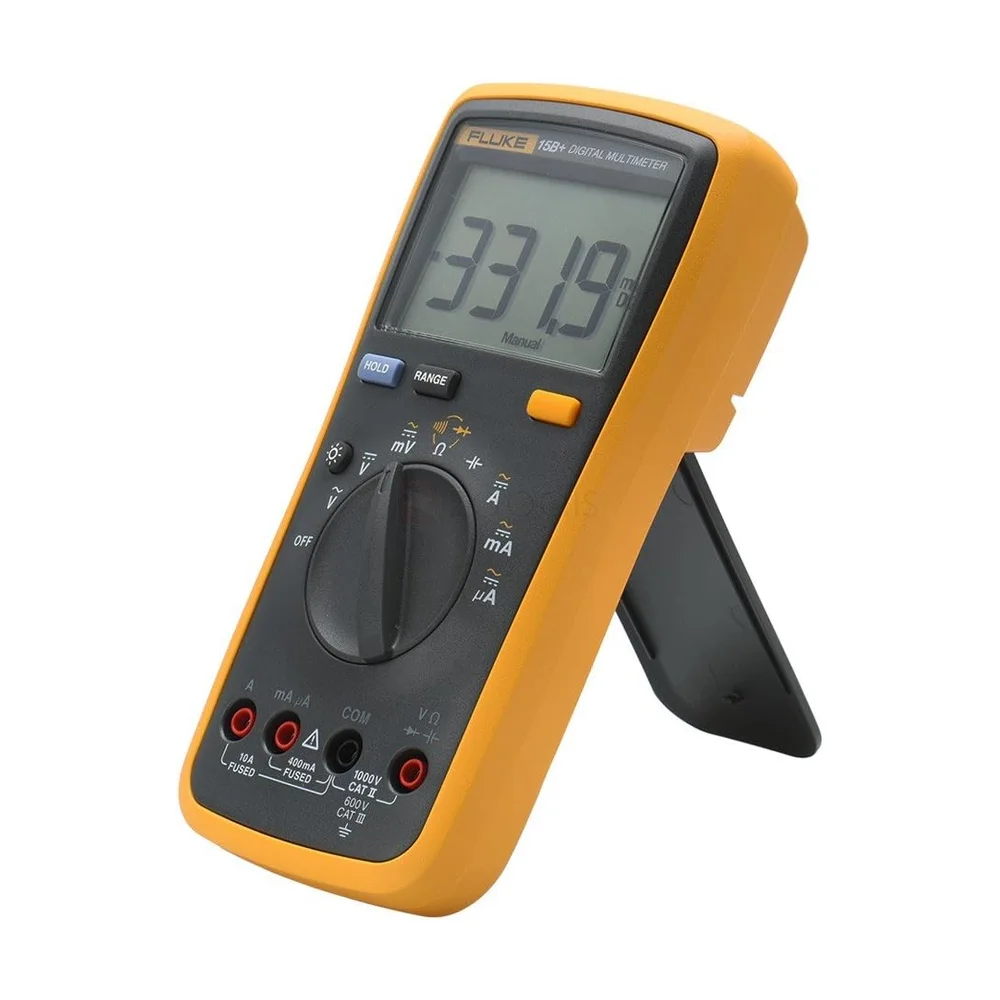
Digital Multimeter DT-830D
Basic 3½ digit DMM, DC/AC voltage + current, resistance, hFE, diode test. Probes included.
 Out of stock
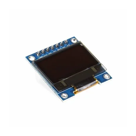
0.96 Inch Blue SPI OLED Display Module 7-Pin 128×64 – SSD1306
[LED/LCD Display] 0.96 Inch Blue SPI OLED Display Module 7-Pin 128×64 – SSD1306 The 0.96-inch Blue OLED Display Module is a compact graphical display based on the SSD1306 driver IC, featuring a 128×64 pixel resolution and blue monochrome display. This version has a 7-pin interface with a dedicated CS (Chip Select) pin, making it suitable for 4-wire SPI communication. The module is factory-configured for SPI and can also be modified for I2C/IIC communication on compatible board versions. With its compact size, wide viewing angle and low-power OLED technology, it is suitable for Arduino, ESP32, ESP8266, STM32, Raspberry Pi and other microcontroller projects. ⭐ Key Features 0.96-inch blue OLED display 128 × 64 pixel resolution SSD1306 driver IC 7-pin interface Dedicated CS (Chip Select) pin Factory configured for 4-wire SPI Supports SPI and I2C/IIC with appropriate configuration 3.3V/5V compatible on supported module versions No backlight required Low power consumption Wide viewing angle of more than 160° Compact PCB design Pre-soldered 7-pin male header Compatible with Arduino, ESP32, ESP8266, STM32 and Raspberry Pi projects 📋 Technical Specifications Display Type: OLED (Organic Light-Emitting Diode) Display Colour: Blue Display Size: 0.96 inch Driver IC: SSD1306 Resolution: 128 × 64 pixels Interface: SPI / I2C Default Interface: 4-wire SPI Input Voltage: 3.3V–5V Viewing Angle: >160° Module Dimensions: Approximately 27 × 27 × 4mm Operating Temperature: Approximately -30°C to +70°C Header: 7-pin male header, pre-soldered Display Type: Monochrome blue OLED 🔌 7-Pin Interface The 7-pin version provides the following connections: GND – Ground VCC – Power supply D0 / SCK / CLK – SPI clock D1 / MOSI / SDA – SPI data RES / RST – Display reset DC / A0 – Data/Command selection CS – Chip Select 🛠️ SPI Connection The module is normally supplied in 4-wire SPI configuration. For an Arduino Uno, a typical connection is: VCC → 5V GND → GND D0 → SCK / D13 D1 → MOSI / D11 RES → Digital I/O DC → Digital I/O CS → Digital I/O The dedicated CS pin allows the OLED to share the SPI bus with other devices such as SD cards or additional SPI peripherals. 🔄 I2C / IIC Configuration On compatible versions, the module can be converted from SPI to I2C by changing the appropriate resistor configuration on the PCB. The supplied board configuration may require: Moving the resistor from R3 to R1 Shorting R8 with solder Using D0 as SCL Using D1 as SDA Configuring DC for the I2C address The exact resistor positions can vary between board revisions, so check the markings on your particular PCB before modification. 🎯 Applications Arduino projects ESP32 projects ESP8266 projects STM32 development Raspberry Pi projects IoT devices Sensor displays Voltage/current meters Battery monitors Temperature displays Digital clocks Data loggers Portable electronic devices Robotics DIY measuring instruments Embedded systems Menu and status displays 💡 Advantages of OLED OLED technology is self-emissive, meaning the pixels produce their own light and do not require a conventional backlight. This provides high contrast, compact construction and a wide viewing angle while keeping power consumption relatively low. ⚠️ Important Notes This is the 7-pin SPI version, not the 6-pin version. The module is normally configured for SPI communication. Check the PCB labels before connecting the module. Do not exceed the specified supply voltage. Although many versions support 5V operation, the exact voltage tolerance can vary between board revisions. I2C operation may require hardware resistor modification. The actual PCB layout and component markings may vary slightly between production batches. Display colour: Blue. Libraries such as Adafruit SSD1306 and U8g2 can be used with compatible microcontrollers. 📦 Package Includes 1 × 0.96 Inch Blue SPI OLED Display Module
 Out of stock
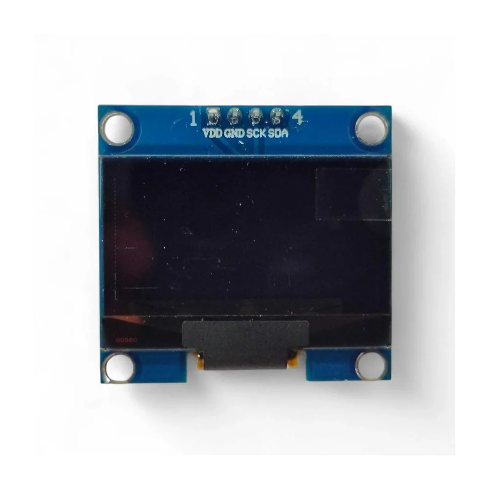
1.3 Inch I2C IIC 128×64 OLED Display Module – White
[LED/LCD Display Module] The 1.3 Inch I2C 128×64 OLED Display Module is a compact, high-contrast display designed for Arduino, ESP32, NodeMCU, Raspberry Pi, and other microcontroller-based projects. This module uses OLED (Organic Light Emitting Diode) technology, providing bright white pixels with excellent contrast and wide viewing angles. Powered by the SSH1106 controller chip, the display offers smooth graphics rendering and reliable performance. With a resolution of 128×64 pixels, it can display text, graphics, icons, and sensor data clearly even in small embedded systems. The module communicates using the I2C (IIC) interface, requiring only 4 pins (VCC, GND, SDA, SCL), which helps save valuable GPIO pins on your microcontroller. It operates within a voltage range of 3.3V to 5V, making it compatible with most development boards. Unlike traditional LCD displays, OLED displays do not require a backlight because each pixel emits its own light. This results in lower power consumption, better contrast, and faster response times. Due to its compact size, lightweight design, and simple wiring, the display module is ideal for IoT devices, sensor monitors, battery indicators, portable electronics, robotics projects, and DIY electronics applications. ⭐ Features 1.3 Inch OLED Display Module 128 × 64 pixel resolution White pixel display SSH1106 display controller I2C / IIC communication interface Requires only 4 pins High contrast and wide viewing angle Low power consumption Compatible with Arduino, ESP32, NodeMCU, Raspberry Pi Ideal for embedded and IoT projects 🔧 Technical Specifications Display Size: 1.3 inch Resolution: 128 × 64 pixels Controller Chip: SSH1106 Display Area: 34.5 × 19 mm Interface Type: IIC / I2C Pixel Color: White Driving Voltage: 3.3V – 5V Operating Temperature: -40°C to 70°C Physical Dimensions Length: 35.5 mm Width: 33.5 mm Height: 4 mm Weight: 7 g 📦 Package Includes 1 × 1.3 Inch 128×64 OLED Display Module (White)
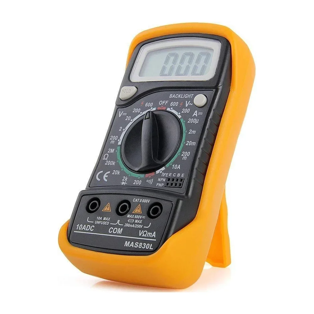
MAS830L Digital LCD Multimeter with Backlight | AC/DC Voltage Current Resistance Tester
[Measuring Instruments] The MAS830L Digital LCD Pocket Multimeter with Backlight is a compact, accurate, and reliable electrical measuring instrument designed for everyday testing and troubleshooting. Built for technicians, students, hobbyists, and DIY electronics users, this multimeter supports measurement of AC voltage, DC voltage, DC current, resistance, continuity, and diode testing in a convenient handheld format. Equipped with a clear LCD display and built-in backlight, the MAS830L allows easy reading of measurements even in low-light working conditions. Its manual range selector dial provides simple and precise control over measurement ranges, while automatic polarity indication helps prevent reading errors. Designed with durability and portability in mind, this pocket-size multimeter features a strong impact-resistant body and lightweight construction, making it ideal for both field work and bench testing. The included test leads allow immediate use for checking batteries, circuits, wiring, power supplies, and electronic components. With stable performance, essential protection features, and user-friendly operation, the MAS830L is an excellent choice for electrical maintenance, electronics repair, lab experiments, educational training, and home diagnostics. Whether you are testing voltage, checking continuity, or measuring resistance, this multimeter delivers dependable results at an affordable price. ⭐ Key Features ✔ Measures AC & DC Voltage ✔ Measures DC Current ✔ Resistance Measurement ✔ Continuity Test with Buzzer ✔ Diode Test Function ✔ LCD Display with Backlight for low-light use ✔ Compact pocket-size design ✔ Manual range selection for accuracy ✔ Automatic polarity indication ✔ Lightweight and portable ✔ Ideal for beginners and professionals 🔧 Technical Specifications Model: MAS830L Display: LCD Digital with Backlight Display Count: 3½ digit (1999 count) Range Selection: Manual Polarity: Automatic indication Low Battery Indicator: Yes Measurement Ranges DC Voltage: 200mV / 2V / 20V / 200V / 600V AC Voltage: 200V / 600V DC Current: 200µA / 2mA / 20mA / 200mA / 10A Resistance: 200Ω / 2kΩ / 20kΩ / 200kΩ / 2MΩ Test Functions Continuity with buzzer Diode test Transistor hFE test (model variant dependent) Power Supply: 9V Battery (6F22) Operating Temperature: 0°C to 40°C (typical) Form Factor: Handheld / Pocket Body Material: Impact-resistant plastic 🎯 Applications Electrical troubleshooting Electronics repair & assembly Battery testing Circuit diagnostics DIY electronics projects Educational laboratories Home & industrial maintenance 📦 Package Includes 1 × Unity MAS830L Digital Multimeter 1 × Test Lead Pair 1 × User Manual (if included by batch)
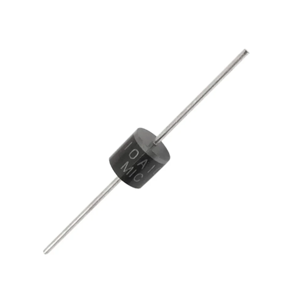
10A10 1000V 10A Silicon Rectifier Diode
[Diode] 10A10 – 1000V 10A Silicon Rectifier Diode 10A10 – 1000V 10A Silicon Rectifier, 10A axial rectifier diode with fast switching times suitable for general applications where a high current is required. Features/Specs: Part No: 10A10 Manufacturer: MIC (Master Instrument Corporation) High surge current capability Low leakage Low forward voltage drop High current capability Low lost Vr – Reverse Voltage: 1000 V If – Forward Current: 10 A Type: Standard Recovery Rectifiers Configuration: Single Vf – Forward Voltage: 1.1 V Ir – Reverse Current: 10 uA Operating Temperature: – 55 C to + 150 C Mounting Style: Through Hole Package/Case: R-6 Datasheet: 10A10 Datasheet Package Includes: 1 x 10A10 – 1000V 10A Silicon Rectifier Note: Product Images are shown for illustrative purposes only and may differ from the actual product.
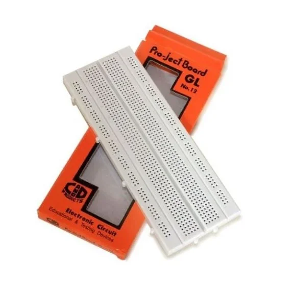
GL-12 840 Points Solderless Breadboard
[Breadboard and Zero PCBs] A GL-12 840 Points Solderless Breadboard is an invaluable tool for experimenting with circuit designs whether in the R&D or university lab. A breadboard is used to make up temporary circuits for testing or to try out an idea. No soldering is required so it is easy to change connections and replace components. Parts will not be damaged so they will be available for re-use afterward. 840 Tie points – 128 Groups of 5 connected terminals, 8 Bus of 25 connected terminals Reusable for fast build a prototype of an electronic circuit – will accept transistors, diodes, LEDs, resistors, capacitors and virtually all types of components – No soldering required – Can modify or revise the circuits easily Fit for jumper wire of 0.8mm diameter – Standard 2.54mm hole spacing Adhesive sheet on the back side of the board – Multiple breadboards can be spliced together too. Features: 100% brand new and high quality Practical and useful Solderless breadboard with 840 points Completely reusable and have a self-adhesive back Easy component placement Package Includes: 1 x GL-12 840 Points Solderless Breadboard
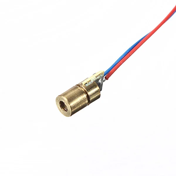
650nm 6mm 3V DC 5mW Mini Laser Dot Diode Module
[Laser Module] 650nm 6mm 3V DC 5mW Mini Laser Dot Diode Module which is made of copper plastic. It is suitable for 3V 5mW standard, with 6mm outside diameter, can be used to connect diode tubes for multiple uses. Features- Output Power: 5mW Working Voltage: 3V DC Working temperature: -10 ℃~+40 ℃ Housing material: Copper Working life: more than 2000 hours Spot mode: Dot Facula (continuous output) Laser wavelength: 650nm red-colored. Operating current: <40mA Power lead length: 120mm Package Includes : 1 x 650nm 6mm 3V DC 5mW Mini Laser Dot Diode Module
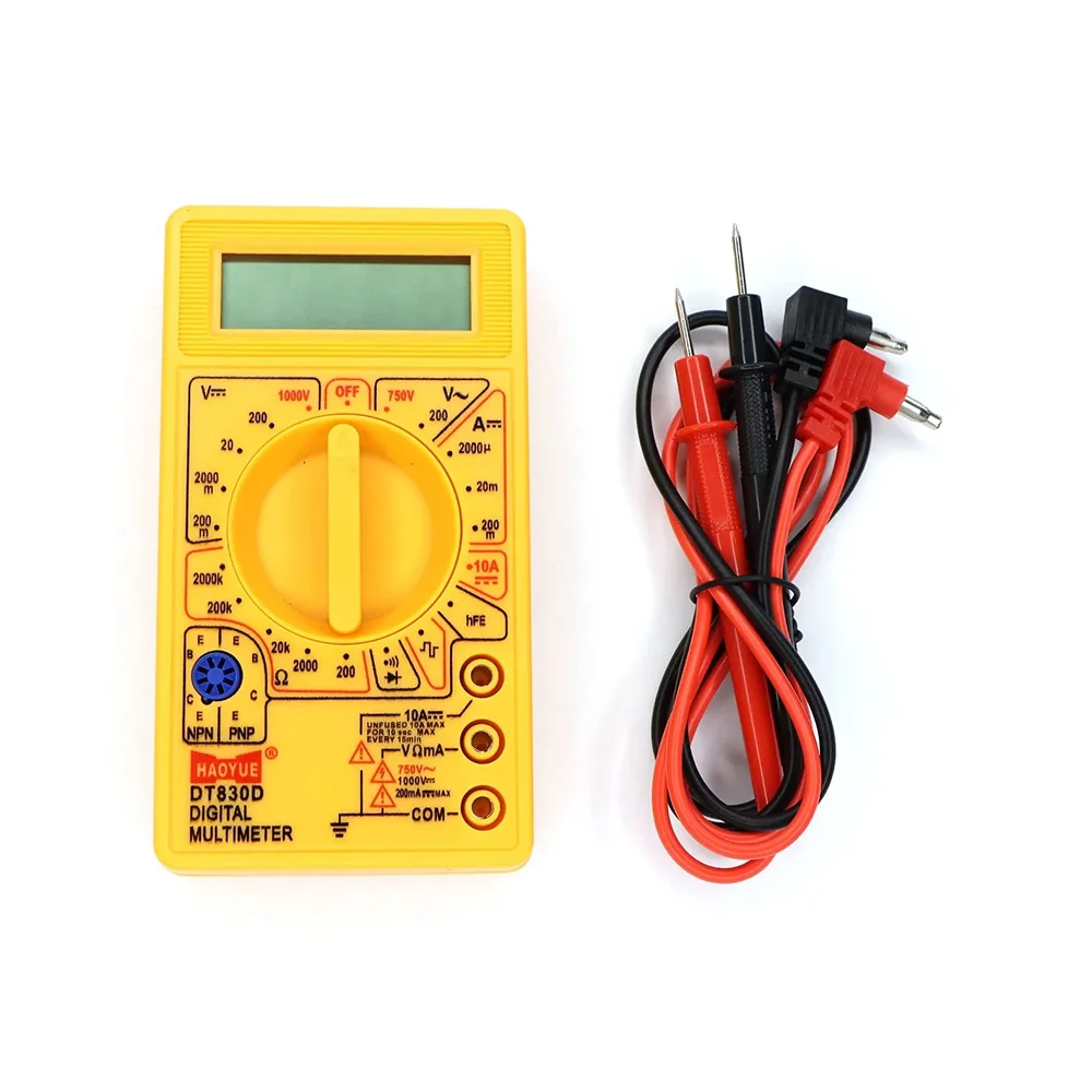 Out of stock
Digital Multimeter Small Yellow Color LCD AC DC Measuring Voltage Current
[Measuring Instruments] A multimeter or a multitester, also known as a VOM (Volt-Ohm meter), is an electronic measuring instrument that combines several measurement functions in one unit. A typical multimeter would include basic features such as the ability to measure voltage, current, and resistance. Analog multimeters use a microammeter whose pointer moves over a scale calibrated for all the different measurements that can be made. Digital multimeters (DMM, DVOM) display the measured value in numerals, and may also display a bar of a length proportional to the quantity being measured. Digital multimeters are now far more common than analog ones, but analog multimeters are still preferable in some cases, for example when monitoring a rapidly-varying As the name suggests it is the multifunction device for all your testing need for daily work. When testing DC voltage, AC voltage, DC current, resistance, diode, buzzer, and battery, connect the red test lead to “VΩmA” jack and black test lead to “COM” jack, whereas When you need to test the current more than 200mA, connect the red test lead to “‘ 10A≡” jack and black test lead to “COM” jack. And When while testing the temperature, connect the temperature probe to “VΩmA” jack or “COM” jack. When testing the magnifying ratio of the transistor, turn the switch to hFE position and connect the transistor to the eight hole jack available in blue color. For the Square wave output, the frequency is 50Hz, the voltage is approximately 3Vp-p. The output jack is “VΩmA” and “COM” Description Table: Features : Small size makes it comfortable in many areas Brand new product. Good for newbies with basic knowledge of VI. No warranty on this product. No replacement or refund on this product Package Include: 1 x Digital Multimeter Small Yellow color and LCD display 2 x Measuring Probes(Red and Black)
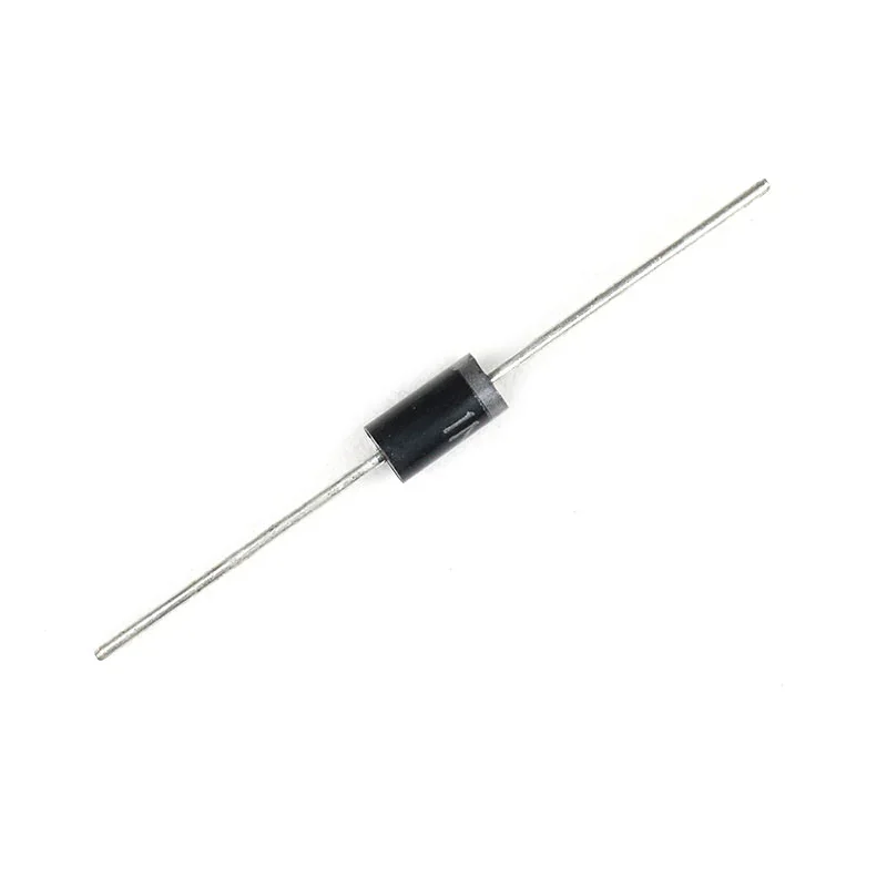
1N5408 3 Amp General Purpose Diode Rapid
[Diode] 1N5408 3Amp Diode is a general-purpose silicon diode. For the protection of various devices, regulating current flow, etc this diode is useful.
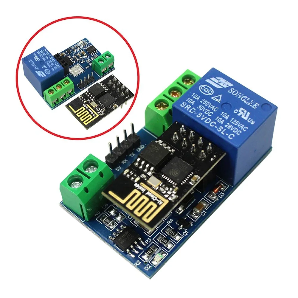
ESP8266 WiFi 5V 1 Channel Relay Module Good Quality
[Relay Module] General Info : Onboard ESP8266 WIFI module, AP mode can be connected at the same time 5 client The module has two ways to work: (i) mobile phone directly mounted on the WIFI module; (ii) mobile phone and WIFI module also carried on the router. How to use : Onboard ESP8266 WIFI module has three operating modes: STA (client), AP (hot), STA + AP (client + hot), according to the work of the module to select the corresponding WIFI module mode of operation The The module needs to use the serial debugging software on the computer and USB to TTL module to send AT commands to configure the WIFI module, USB to TTL module RX, TX, GND pin, then the module on the TX, RX, GND pin, IN +, IN – 5V power supply. Usage Instructions 1) Hardware Connection: Insert the pre-programmed ESP-01/01S module into the onboard 2×4 pin female header (as shown in the diagram below). 2) Power Supply : Connect a DC 5V-12V power source to the module, with the positive terminal to VCC and the negative terminal to GND. 3) Mobile WiFi Connection : Open your phone's WLAN settings, search for and connect to the ESP8266-XXXX hotspot (default password: 12345678). 4) Launch Control APP : Run the pre-installed ESP8266 Controller application on your Android phone. 5) Configure IP Address : Enter the default IP address: 192.168.1.1 in the APP to remotely control the relay switch via your phone. Transmission distance: Open environment, the mobile phone mounted on the WIFI module when the maximum transmission distance of 400m. When the WiFI module and mobile phone at the same time carried on the router when the transmission distance according to the router’s signal weakly; Board function description : IN +, IN-: 5V power input; TX, RX, GND: Serial debug pin; Onboard the ESP8266 WIFI module has three work modes: STA (client), AP (hot), the STA + Ap( hot +client), according to the workings of a module to the corresponding choice of WIFI module working mode. Module need before use serial debugging software and USB to TTL module send serial command was carried out on the WIFI module configuration (don’t power outages after configuration is complete, as some of the parameters of WIFI module cannot be saved when the power is cut off), mobile phone and WIFI module after establishing a network connection can use the phone APP control relay. Control Commands : When cell phone equipped with WiFi module sends commands in the following order: (The default baud rate 115200) AT+CWMODE=2, namely AP mode is selected. AT+RST, reset. AT+CIPMUX=1, open multiple connections. AT+CIPSERVER=1,8080, configure the TCP server, set the port. AT+CIOBAUD=9600 set the baud rate to 9600. (working in relays to control the baud rate 9600). AT+CIFSR to view the AP mode IP address, such as the APIP, “192.168.4.1”. Cell phone WIFI signal connection name starts with AI-THINKER or ESP8266. In the “TCP connection” address and port into the APP, such as 192.168.4.1 and 8080. Click on the grey box relays can be controlled. Features: Onboard Module: ESP8266 wifi module; in AP mode it can connect with 5 Clients at the same time Operating Way: cellphone carried on wifi module; cellphone and wifi module carried on the same router, and use the APP to control relay Diode effusion protection. Short response time
 Out of stock
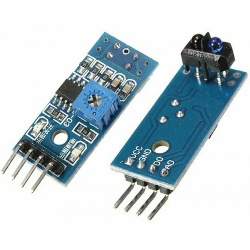
TCRT5000 DUAL LINE TRACKING SENSOR MODULE
[IR and PIR Sensors] This IR reflective sensor Module TCRT5000 IR Sensor is used to detect colour and distance. This sensor module consists on an IR transmitter & an IR receiver. IR Transmitter continuously emits IR signal which is then reflected by an obstacle and is then detected by the IR receiver. TCRT5000 Infrared Reflective Sensor Module is often used in line following robots ,object sorting Robot because this module can sense if a surface is white or black. The measuring distance range from 1mm to 8mm, and the central point is about 2.5mm. There is also an on-board potentiometer to adjust the sensitivity. The infrared diode will emitting the infrared continually when the module is powered ON, when the emitted infrared light has not been reflected or the strength is not big enough, the receiver diode will in the off state and output pin i.e. DO will be LOW. Description of Line Tracking sensor TCRT5000L:- Main chip: LM393, Designed with reflected infrared sensor, indicator light. Built in a potentiometer for sensitivity control. On-board LM393 voltage comparator chip and infrared sensing probe TCRT5000L Support 5 V / 3.5 V voltage input On-board signal output instructions, output is high effective signal at the same time, the indicator lamp light output signal can be directly and single-chip microcomputer IO connection & mid dot; Signal detection sensitivity can adjust Reserve all the way more circuits (P3 voltage drawn) using TCRT5000 infrared reflection sensor test reflection distance: 1 mm to 25 mm Operation voltage: 3.5v-5V Operation current: >15mA wide voltage LM393 comparator output form: digital switch output (0 and 1) a fixed bolt hole, convenient installation. Features of Line Tracking sensor TCRT5000:- Product Name : Infrared Obstacle Avoidance Sensor Module; Module Model : TCRT5000; Working Voltage : DC 3.5-5V Output Channel : 0/1; Detect Distance : 1-25mm; Focal Distance : 2.5mm Chipset : LM393; PCB Size : 32 x 14mm/1.3″ x 0.55″ (L*W) Total Size : 38 x 14 x 18mm/1.5″ x 0.55″ x 0.7″(L*W*H); Material : Electric Part Package Content : 1 x Infrared Obstacle Avoidance Sensor Module
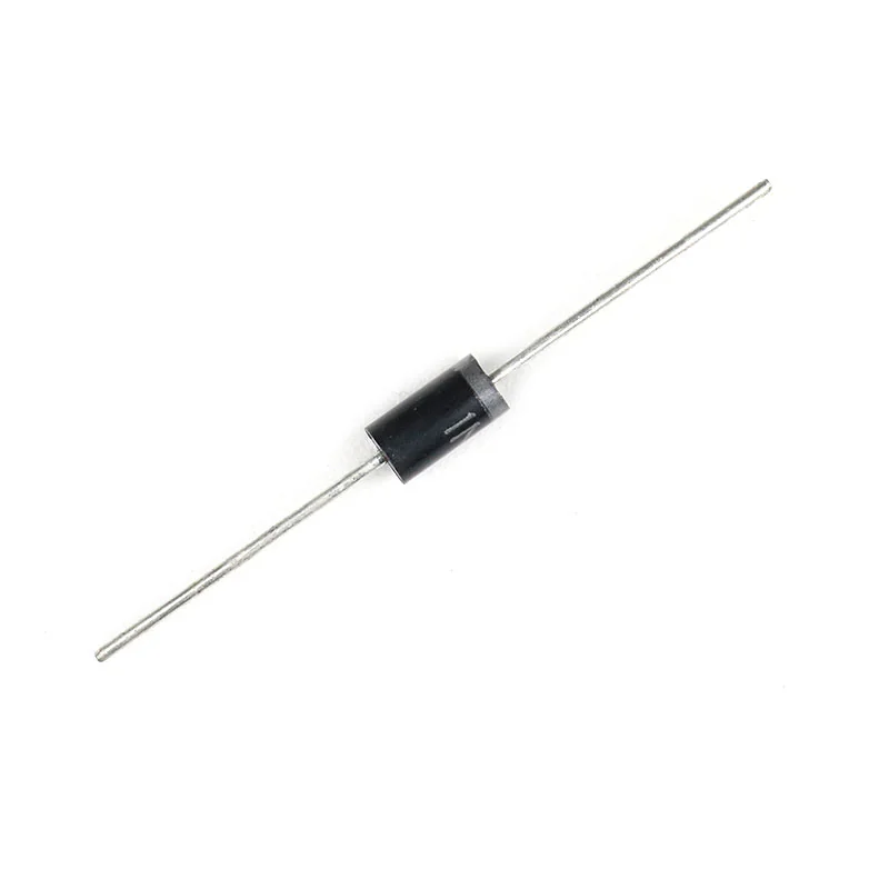
1N4007 General Purpose Rectifier Diode DO-41 (Through Hole) Made RAPID
[Diode] 1N 4007 – 1A General Purpose Rectifier Axial 4007 Diode 1N4007 is a rectifier diode, designed specifically for circuits that need to convert alternating current to direct current. It can pass currents of up to 1 A, and have a peak inverse voltage (PIV) rating of 1,000 V. Characteristics: Maximum Recurrent Peak Reverse Voltage 1000V Maximum RMS Voltage 700V Maximum DC Blocking Voltage 1000V Average Forward Current: 1.0A Peak Forward Surge Current: 30A Maximum Instantaneous Forward Voltage: 1.0V Maximum DC Reverse Current At Rated DC Blocking Voltage: 5.0µA @ 25°C Typical Junction Capacitance: 15pF Typical Reverse Recovery Time: 2.0us Mounting Type: Through Hole Operating Temperature: -55°C ~ 150°C Useful Resources:
 Out of stock
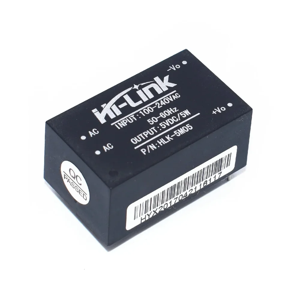
Hi Link HLK 5M05 5V/5W Switch Power Supply Module
[Power Supply] HLK-5M05 5V/5W Switch Power Supply Module is plastic enclosed PCB mounted isolated switching step-down power supply module. It can supply 5V DC from 120V AC – 230V AC and has a power rating of 5 Watt. This makes it perfect for small projects that need a 5 volt supply from mains. This power supply module replaces lots of parts from the traditional power supply like diodes, voltage regulator and transformers. Therefore there are many advantages for these modules, such as low-temperature rise, low power, high efficiency, high reliability, high-security isolation etc. This Power Supply Module voltage source is a switching source, so you do not have to worry about fluctuations in voltage grid. It is designed to be mounted on the PCB and is the ideal solution to power pads that you take. It is widely used in a smart home, automation and control, communication equipment, instrumentation and other industries. Features: Meet UL, CE requirements, Ultra-thin, ultra-small All voltage input (AC: 90 ~ 264V) Low ripple and low noise Output overload and short circuit protection High efficiency, high power density The product is designed to meet the requirements of EMC and Safety Test Low power consumption, environmental protection, no-load loss <0.1W Environmental conditions: Technical indicators: Single bit Working temperature: – 20-60 +degree Storage temperature: + 80-40 -degree Relative humidity: 5-95% The cooling way: Natural cooling The atmospheric pressure: 80-106Kpa The altitude: 2000M or less. Package Includes: 1 x HLK-5M05 5V/5W Switch Power Supply Module
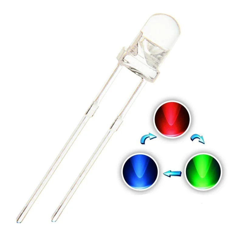
Red/White Led 5mm 2 Pin Auto Flashing
[DIP LED] These is the very common Two Color Auto Flashing LEDs which is used in all types of electronic projects. These Light Emitting Diodes feature a 5mm diameter head, 2 pin terminal for a reliable connection. It can give out the chosen color light when powered on. Ideal for color displays, indicators, diagnostic or analytical equipment and etc. Colour:- Super Bright Two-Colour Outer Diameter: 5mm Round Current: 20mA, Color Red, Greed Polarity: Anode (Longer Part) | Cathode (Shorter Part) It is great for electronic and electrical experiments Auto Flashing Red, Green LED VF- 3.20 – 3.40V
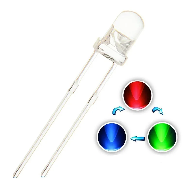
RGB Led 5mm 2 Pin Auto Flashing
[DIP LED] These is the very common Tri Color Auto Flashing LEDs which is used in all types of electronic projects. These Light Emitting Diodes feature a 5mm diameter head, 2 pin terminal for a reliable connection. It can give out the chosen color light when powered on. Ideal for color displays, indicators, diagnostic or analytical equipment and etc. Colour:- Super Bright Tri-Colour Outer Diameter: 5mm Round Current: 20mA, Color R G B Polarity: Anode (Longer Part) | Cathode (Shorter Part) It is great for electronic and electrical experiments Auto Flashing RGB LED VF- 3.20 – 3.40V
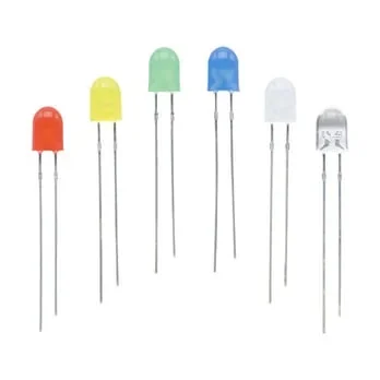
Good Quality Oval Diffused 5mm LED
[DIP LED] Features and Specifications : Product : LED Diode (Light Emitting Diode) Light Colour : Red/Green/Blue/Yellow LED Type : 5mm PRODUCT WAVE LENGTH/NM MCD VOLTAGE CURRENT 5mm Yellow 588-590nm 300-400mcd 2.0-2.2v 20mA 5mm White 6000-15000k 14000-16000mcd 3.0-3.2V 20mA 5mm Red 620-625nm 400-500mcd 1.8-2.0V 20mA 5mm Blue 460-465nm 600-800mcd 3.0-3.2V 20mA 5mm Green 570-572nm 400-500mcd 1.8-2.0V 20mA Good Quality oval Diffused 5mm LED
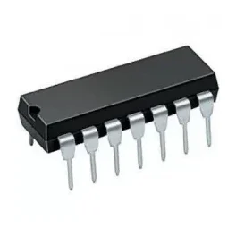 Out of stock
74HC47 or 74LS47 IC BCD to seven segment decoder driver
[Logic Gates IC] 7447 or 74LS47 decodes BCD into 7 Segments, which means it accepts a binary coded decimal or BCD Values as input and decoded into a pattern that drives a 7-segment for displaying digits 0 to 9, so its name is BCD to 7 segment driver or decoder. Its input is 4 lines BCD data and generates complements as output. The generation of complement data of BCD is internally so no coding or programming is required to generate it. Specification Large Voltage range Has open collector output which directly drives indicator Has a wide range of operating conditions No need for external resistors because of internal pull-ups No high-speed termination because of the input clamp diode 4 the number of input lines and 7 output lines Pin Description BCD input 2 BCD input 3 LT RBO RBI BCD input 4 BCD input 1 GND E D C B A G F VCC
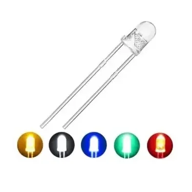
Good Quality Transparent 5mm LED
[DIP LED] Features and Specifications : Product : LED Diode (Light Emitting Diode) Light Colour : Red/Green/Blue/Yellow/White LED Type : 5mm PRODUCT WAVE LENGTH/NM MCD VOLTAGE CURRENT 5mm Yellow 588-590nm 300-400mcd 2.0-2.2v 20mA 5mm White 6000-15000k 14000-16000mcd 3.0-3.2V 20mA 5mm Red 620-625nm 400-500mcd 1.8-2.0V 20mA 5mm Blue 460-465nm 600-800mcd 3.0-3.2V 20mA 5mm Green 570-572nm 400-500mcd 1.8-2.0V 20mA Good Quality Transparent 5mm LED
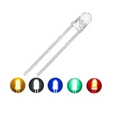
Good Quality Transparent 3mm LED
[DIP LED] Features and Specifications : Product : LED Diode (Light Emitting Diode) Light Colour : Red/Green/Blue/Yellow/White LED Type : 3mm PRODUCT WAVE LENGTH/NM MCD VOLTAGE CURRENT 3mm Yellow 588-590nm 300-400mcd 2.0-2.2v 20mA 3mm White 6000-15000k 14000-16000mcd 3.0-3.2V 20mA 3mm Red 620-625nm 400-500mcd 1.8-2.0V 20mA 3mm Blue 460-465nm 600-800mcd 3.0-3.2V 20mA 3mm Green 570-572nm 400-500mcd 1.8-2.0V 20mA Good Quality Transparent 3mm LED
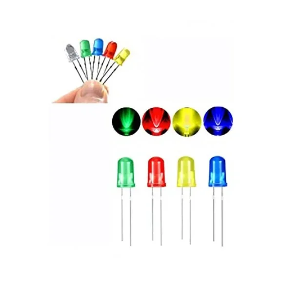
Good Quality Diffused 5mm LED
[DIP LED, LED LIGHT] Features and Specifications : Product : LED Diode (Light Emitting Diode) Light Colour : Red/Green/Blue/Yellow LED Type : 5mm PRODUCT WAVE LENGTH/NM MCD VOLTAGE CURRENT 5mm Yellow 588-590nm 300-400mcd 2.0-2.2v 20mA 5mm White 6000-15000k 14000-16000mcd 3.0-3.2V 20mA 5mm Red 620-625nm 400-500mcd 1.8-2.0V 20mA 5mm Blue 460-465nm 600-800mcd 3.0-3.2V 20mA 5mm Green 570-572nm 400-500mcd 1.8-2.0V 20mA Good Quality Diffused 5mm LED
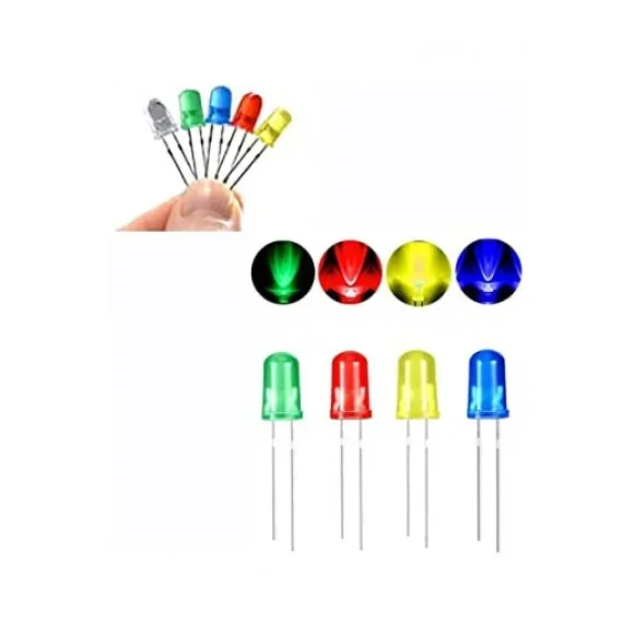 Out of stock
Good Quality Diffused 3mm LED
[DIP LED] Features and Specifications : Product : LED Diode (Light Emitting Diode) Light Colour : Red/Green/Blue/Yellow LED Type : 3mm PRODUCT WAVE LENGTH/NM MCD VOLTAGE CURRENT 5mm Yellow 588-590nm 300-400mcd 2.0-2.2v 20mA 5mm White 6000-15000k 14000-16000mcd 3.0-3.2V 20mA 5mm Red 620-625nm 400-500mcd 1.8-2.0V 20mA 5mm Blue 460-465nm 600-800mcd 3.0-3.2V 20mA 5mm Green 570-572nm 400-500mcd 1.8-2.0V 20mA Good Quality Diffused 3mm LED