
All products · 8 of 1440
Electronics, sensors, robotics kits, PC components, peripherals — everything Unik Systems carries, in one place.
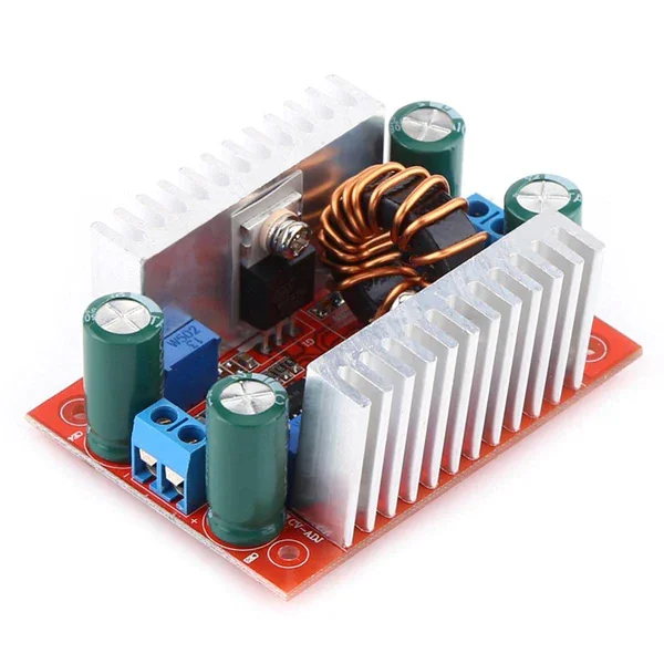
400W DC-DC Step-up Boost Converter Constant Current Power Supply Module LED Driver Step Up Module
[Step UP Buck Converter] This is a great 400W DC to DC step-up power supply module for electric equipment, digital products, laptop, etc. Input and output are designed with screw terminals for convenient wire connection and disconnection. High efficiency, the maximum conversion efficiency can be 96% and efficiency is related to input/output voltage, current and voltage difference. There are 2 heat sinks that would ensure a better heat dissipation. It can also be used as a driver for high power LED lights or voltage regulator for solar panels. Features: Input and output are designed with screw terminals for convenient wire connection and disconnection. High efficiency, the maximum conversion efficiency can be 96% and efficiency is related to input/output voltage, current and voltage difference. There are 2 heat sinks that would ensure a better heat dissipation. It can also be used as a driver for high power LED lights or voltage regulator for solar panels. Output Voltage/Current Adjustment: Adjust "CV-ADJ" potentiometer clockwise to reduce voltage, counterclockwise to increase voltage. Adjust "CC-ADJ" potentiometer counterclockwise about 30 circles to minimize the output current before connecting to load(clockwise to increase current, counterclockwise to reduce current). Then adjust "CC-ADJ" clockwise to the current value you need. If you use the module for battery charging, connect to output after battery is fully discharged. Because if the more energy is left in battery, the less charging current will be. Specification: Input Voltage: DC 8.5V to 50V Output Voltage: DC 10V to 60V Max. Input Current: 15A Max. Output Current: 12A Quiescent Current: 10mA Constant Current Range: 0.2A to 12A Operating Temperature: -40° to 85° Package Included: 1 x Boost Module 400W DC-DC Step-up Boost Converter Constant Current Power Supply Module 15A Step-Up LED Driver
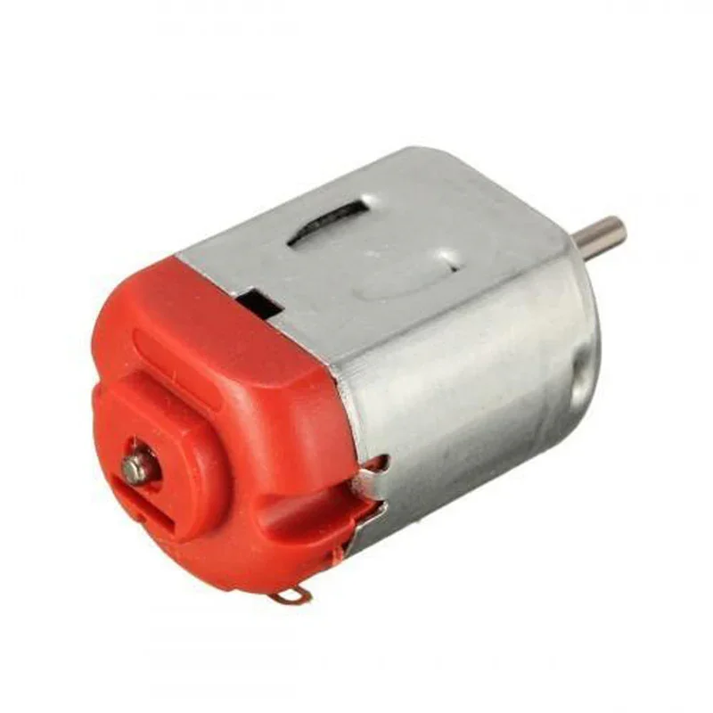
Micro 130 DC Motor 3V-6V High Speed Brushed DC Motor (9000–13000 RPM)
[General DC Motor] The Micro 130 DC Motor is a compact, lightweight, and high-performance brushed DC motor widely used in hobby electronics, robotics, educational kits, and battery-powered devices. Operating on 3V to 6V DC, it delivers a no-load speed of 9,000–13,000 RPM, making it suitable for applications requiring high-speed rotary motion in a compact form factor. Designed with a durable metal housing and a precision 2mm output shaft, this motor provides smooth operation, stable performance, and excellent reliability. Its compact dimensions make it easy to integrate into small electronic projects where space is limited. The motor can be easily connected to Arduino, Raspberry Pi, ESP32, motor driver modules, and other microcontroller platforms, making it an excellent choice for beginners, students, hobbyists, and professionals. Whether you're building a robot, smart car, mini fan, science experiment, or replacing a toy motor, the Micro 130 DC Motor offers dependable performance and long service life. ⭐ Features Compact and lightweight Micro 130 brushed DC motor Operating voltage from 3V to 6V DC High-speed operation up to 13,000 RPM Durable metal housing for long service life Precision 2mm output shaft Smooth and stable performance Low power consumption Easy two-wire connection Supports clockwise and counter-clockwise rotation Ideal for battery-powered applications Perfect for DIY electronics, robotics, and educational projects 📋 Technical Specifications Product Type: Brushed DC Motor Model: Micro 130 Operating Voltage: 3V – 6V DC Motor Speed: 9,000–13,000 RPM (No Load) Motor Type: Brushed DC No Load Current: 0.5A – 0.9A Shaft Diameter: 2mm Shaft Length: 8mm Rotation Direction: Clockwise (CW) / Counter-Clockwise (CCW) by reversing supply polarity Terminal Type: Solder Tabs Housing Material: Metal Weight: Approx. 18g 🔧 Applications The Micro 130 DC Motor is suitable for a wide range of applications, including: Robotics Projects Arduino Projects Raspberry Pi Projects ESP32 Projects RC Cars Toy Vehicles DIY Electronics Mini Cooling Fans Small Water Pumps Educational STEM Kits Science Experiments Battery-Operated Devices Automation Projects Prototype Development Hobby Electronics 📦 Package Includes 1 × Micro 130 DC Motor (3V–6V)Note: Product images are for reference only. The actual product may differ slightly due to manufacturing revisions or supplier changes. For bulk purchases, we recommend ordering a sample first or contacting customer support to verify the latest product images and specifications.
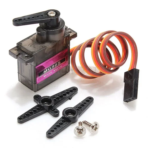
TowerPro Metal Gear MG90S Mini Digital Servo Motor (180° Rotation)
[Servo Motor] ⚙️ TowerPro MG90S Mini Digital Metal Gear Servo Motor (180°) Metal Gear • Digital Servo • 180° Rotation • High Precision • Ideal for RC & Robotics The TowerPro MG90S Mini Digital Servo Motor is a compact, high-performance 9g metal gear servo designed for precise position control in robotics, RC models, automation, and DIY electronics projects. Equipped with all-metal gears, a digital control circuit, and high positioning accuracy, the MG90S offers greater durability, faster response, and higher torque than standard plastic gear servos. Operating from 4.8V to 6.0V DC, the servo delivers a stall torque of up to 2.2 kg·cm and a rotation angle of approximately 180°, making it ideal for robotic arms, pan-tilt camera systems, RC airplanes, RC cars, boats, educational kits, and embedded control applications. The standard 3-wire JR/Futaba-compatible connector allows direct interfacing with Arduino, ESP32, Raspberry Pi, STM32, and most RC receivers. Its lightweight design, compact dimensions, and excellent holding torque make the MG90S one of the most popular micro servos for hobbyists, students, and professionals alike. ⭐ Features Genuine TowerPro MG90S digital servo Durable all-metal gear transmission Approximate 180° rotation angle High positioning accuracy Fast control response High holding torque Smooth and quiet operation Lightweight and compact design Standard 3-wire servo interface Compatible with Arduino, ESP32, Raspberry Pi and RC receivers Ideal for robotics, RC models and automation projects 📋 Technical Specifications Product Type: Mini Digital Servo Motor Brand: TowerPro Model: MG90S Gear Type: Metal Gear Rotation Angle: Approximately 180° Operating Voltage: 4.8V–6.0V DC Stall Torque: 1.8 kg·cm @ 4.8V 2.2 kg·cm @ 6.0V Operating Speed: 0.10 sec/60° @ 4.8V 0.08 sec/60° @ 6.0V Control Signal: PWM (50Hz Standard Servo Signal) Dead Band Width: 1µs Connector Type: JR / Futaba Compatible Cable Length: Approximately 25cm Dimensions: 22.8 × 12.2 × 28.5 mm Weight: Approximately 13.4g Operating Temperature: 0°C to +55°C These specifications are consistent with the manufacturer's published specifications. 🔧 Applications Suitable for: Arduino Projects ESP32 Projects Raspberry Pi Projects Robotic Arms Humanoid Robots RC Airplanes RC Cars RC Boats Pan-Tilt Camera Systems Automatic Door Mechanisms DIY Electronics Educational Robotics Smart Automation Projects Mechatronics Projects 📦 Package Includes 1 × TowerPro MG90S Mini Digital Servo Motor 1 × Servo Horn Set Single Arm Horn Double Arm Horn Four Arm Horn 1 × Mounting Screw Set ⚠️ Note Operate the servo only within the recommended 4.8V–6.0V DC supply range. For stable operation, use an external regulated power supply when driving the servo from microcontrollers. Product appearance, cable color, or accessories may vary slightly depending on the manufacturing batch. Counterfeit MG90S servos are common in the market. Purchase from trusted suppliers for genuine performance.
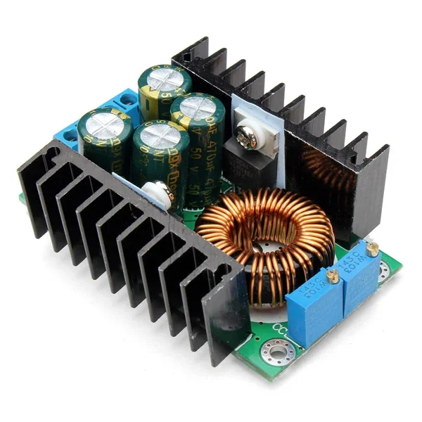
10A 300W DC-DC Step-Down Adjustable Constant Voltage & Constant Current Module XL4016
[Step Down Buck Converter] 10A 300W DC-DC Step-Down Adjustable Constant Voltage & Constant Current Module XL4016 The 10A 300W DC-DC Step-Down Adjustable Constant Voltage & Constant Current Module is a high-power adjustable buck converter designed for applications requiring regulated output voltage and controlled output current. It can be used as a high-power LED driver, battery charging module, regulated power supply, and vehicle power supply. The module features independent CV (Constant Voltage) and CC (Constant Current) adjustment using onboard 3296 multi-turn potentiometers, allowing precise adjustment of the output voltage and current. A dual heatsink design helps dissipate heat from the power components during high-power operation. With a maximum advertised power rating of up to 300W, the module is suitable for high-power applications when adequate cooling and an appropriate input supply are provided. For continuous high-current operation, additional forced-air cooling is recommended. ⭐ Key Features Up to 300W output power 10A maximum output current Adjustable constant voltage and constant current CV and CC independent adjustment Output voltage continuously adjustable Typical output voltage range: 1.25V–35V High-power DC-DC step-down/buck converter Dual heatsink design for improved heat dissipation Independent heatsink for MOSFET/Schottky diode section 3296 multi-turn potentiometers for precise adjustment High-frequency capacitors for reduced output ripple Large Sendust core Double pure-copper winding Suitable for LED driver and battery charging applications Additional cooling recommended for continuous high-power operation 📋 Technical Specifications Product Type: DC-DC Step-Down Buck Converter Function: Constant Voltage / Constant Current Maximum Output Power: Up to 300W Maximum Output Current: 10A Recommended Continuous Current: Up to approximately 8A with additional cooling Output Voltage: Continuously adjustable, approximately 1.25V–35V Minimum Voltage Difference: Approximately 1V Adjustment: CV / CC Multi-Turn Potentiometers Potentiometer Type: 3296 Multi-Turn Operating Temperature: -40°C to +85°C Output Ripple: Approximately 50mV under the stated test conditions Cooling: Dual Heatsink Additional Cooling: Cooling fan recommended for continuous high-power operation Converter Type: Step-Down / Buck 🔧 Applications High-Power LED Driver Constant Current LED Power Supply Lithium Battery Charging Lead-Acid Battery Charging Ni-Cd / Ni-MH Battery Charging 6V Battery Charging 12V Battery Charging 14V Battery Charging 24V Battery Charging Solar Panel Power Systems Wind Generator Applications Vehicle-Mounted Power Supply Laptop Power Supply Regulated DC Power Supply Low-Voltage Power Supply Systems 🎛️ CV & CC Adjustment The module has two independent multi-turn adjustment potentiometers: CV (Constant Voltage): Adjusts the required output voltage. CC (Constant Current): Adjusts the maximum/constant output current. Turn the potentiometers clockwise to increase and anticlockwise to decrease the corresponding setting. Use a reliable multimeter while adjusting the output voltage and current. 🔋 Battery Charger Application Determine the required battery charging voltage and charging current. Connect a suitable DC input supply to the module while observing correct polarity. Use the CV adjustment to set the required charging voltage. Use the CC adjustment to set the required charging current. Connect the battery to the output while observing correct polarity. Monitor the charging process and ensure the voltage and current remain within the battery manufacturer's specifications. 💡 Constant Current LED Driver Application Determine the LED's required operating current and maximum operating voltage. Adjust the output voltage to a low safe level before connecting the LED. Use the CC adjustment to set the required LED current. Adjust the CV setting according to the LED's required operating voltage. Connect the LED and verify the output voltage and current with a multimeter. 🛠️ Adjustment Instructions If the output voltage initially follows the input voltage and cannot be adjusted, turn the appropriate potentiometer counterclockwise for multiple turns and then adjust again. Turn the adjustment potentiometers clockwise to increase and anticlockwise to decrease. Always use a multimeter when setting voltage or current. The potentiometer closest to the output side is specified for CC/current adjustment. The potentiometer closest to the input side is specified for CV/voltage adjustment. 📦 Package Includes 1 × 10A 300W DC-DC Step-Down Adjustable Constant Voltage & Constant Current Module ⚠️ Precautions This is a step-down (buck) converter; the input voltage must be higher than the required output voltage. Do not exceed the module's maximum voltage, current, or power limits. 300W is the maximum advertised power rating; actual continuous power depends on input voltage, output voltage, current, efficiency, and cooling. For continuous high-current operation, use a cooling fan with the heatsink. Do not short-circuit the output. Observe correct input and output polarity. Use appropriate protection when charging batteries. Never leave a battery charging unattended. Ensure the module's heatsink does not become excessively hot during operation.
 Out of stock
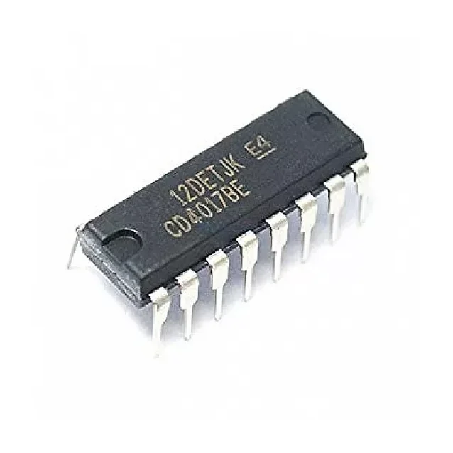
4017 Decade Counter IC
[Timer,Clock,Counter ICs] DESCRIPTION:- This IC 4017 is a 16-pin counter IC. It is a CMOS decade counter cum decoder circuit. It can count from zero to ten and its outputs are decoded. This saves a lot of board space and time required to build our circuits when our application demands using a counter followed by a decoder IC. IC 4017 is a digital counter plus decoder circuit. CD4017 Pin Configuration :- Pin Number Pin Name Description 1 to 7 and 9,10,11 Output pins Q0 to Q9 These are the 10 output pins on which the counting occurs, they are not in order hence verify pin diagram above 8 Vss or Ground Connected to the Ground of the circuit 12 Carry Out (CO) This pin goes high after the IC counts from 1 to 10. This is used as carry while counting. 13 Clock Enable (EN) This is an input which when made high will hold the count at the current state 14 Clock The counting happens when this clock pulse goes high , this pin is normally connected to 555 timer or other uC to produce a pulse 15 Resets As the name suggests this pin resets the count back to 1 16 Vdd / Vcc Connects to the supply voltage typically +5V Features:- High speed 16 pin CMOS Decade counter Supports 10 decoded outputs Wide supply voltage range from 3V to 15V, typically +5V TTL compatible Maximum Clock Frequency: 5.5Mhz Available in 16-pin PDIP, GDIP, PDSO packages Where to use CD4017 IC:- The IC CD4017 is used for counting applications, it has the capability to turn on 10 outputs sequentially in a pre-defined time and reset the count or hold it when required. It also has the capability to indicate the status of counting using Carry pin. This is commonly used for Led chasers and other logical output projects, so if you are looking for a sequential decoded counting IC that can count up to 10 then this IC will be your right choice How to use a CD4017 IC:- The IC can work from 3V to 15V, but normally powered with +5V to the Vdd/Vcc pin and the Ground/Vss pin is connected to ground. We have 10 output pins ranging from Q0 to Q9, these pins can be connected to any load but we are using LEDs here as shown in the circuit below. Package Includes :- 1 X 4017 Decade Counter IC
 Out of stock
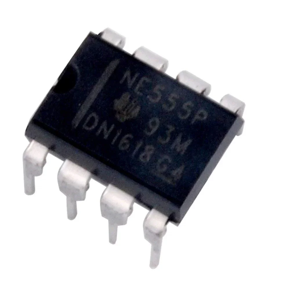
NE 555 P PDIP-8 Timer IC
[Timer,Clock,Counter ICs] The NE 555 P timer IC is a precision timing circuit capable of producing accurate time delays or oscillation. In the time-delay or monostable mode of operation, the timed interval is controlled by a single external resistor and capacitor network. In the as table mode of operation, the frequency and duty cycle can be controlled independently with two external resistors and a single external capacitor. The threshold and trigger levels normally are two-thirds and one-third, respectively, of VCC. These levels can be altered by the use of the control voltage terminal. When the trigger input falls below the trigger level, the flip-flop is set, and the output goes high. If the trigger input is above the trigger level and the threshold input is above the threshold level, the flip-flop is reset and the output is low. Features: Timing from microseconds to hours A stable or monostable operation Adjustable duty cycle TTL compatible output can sink or source up to 200mA Applications: Clock & Timing, Consumer Electronics, Aerospace, Defence, Military, Embedded Design & Development Package Includes: 1 x NE 555 P PDIP-8 Timer IC
 Out of stock
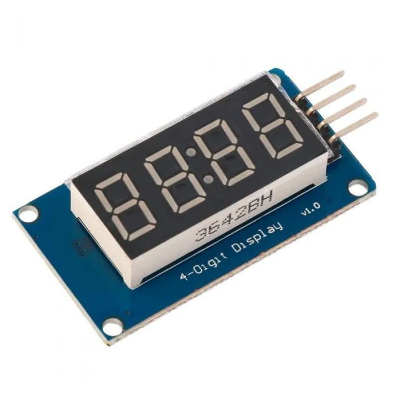
TM1637 4 Digits 7 Segment Led Display Module with Clock for Arduino
[LED/LCD Display Module] The TM1637 4 Digits 7 Segment Led Display Module with Clock for Arduino is an affordable solution for displaying the output data of your Arduino project. Though the data displayed is restricted by numbers still it allows users to display some characters too like A, B, C etc. This 7 segment LED Display has 4 digits which are controlled by TM1637 Driver Chip. It requires only two connections to control this TM1637 4 Digits 7 Segment Led Display Module. Also thanks to the I2C Bus you can control it using only 2 wires, leaving more pins available on your MicroController to connect other things. The module is a 12-foot clock with four common anode tube (0.36 inch) display module for driver IC TM1637, only two signal lines can make the MCU control four 7-segment digital tubes. .Pinout Description of TM1637 4 Digits 7 Segment Led Display Module with Clock for Arduino :- LED Display module to Arduino- GND – GND Vcc – 5V DIO – D2 CLK – D3 Features of TM1637 4 Digits 7 Segment Led Display Module with Clock for Arduino:- Ease to use. Ease of multiplexing. Can use as a 4 digit display unit. Can use as a clock display. DIY clock project. 4 digit display unit. Electrical/Electronic projects. The counter project using 7 segment display. 4 M2 screws positioning holes for easy installation Package Includes:- 1 x TM1637 4 Digits 7 Segment Led Display Module with Clock for Arduino. * Product Images are shown for illustrative purposes only and may differ from actual product.
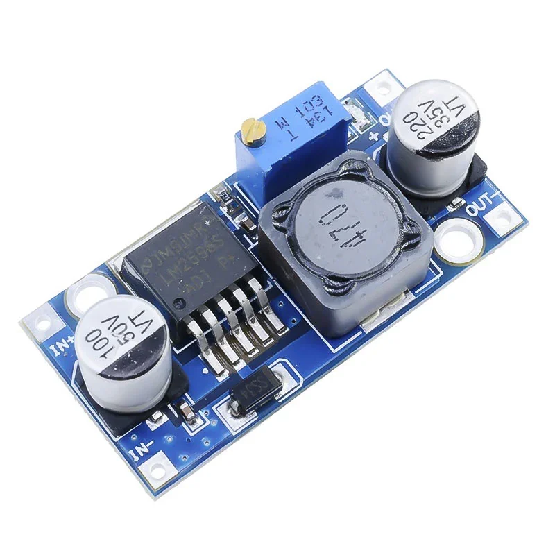
LM2596 DC-DC Buck Converter 4.5-40V to 3-35V Adjustable Step Down Module
[Step Down Buck Converter] Introducing a high-performance DC to DC Step Down Adjustable Power Supply Module, built upon the newly developed LM2596S Wide Range Switching Regulator. With dimensions approximately 43 x 20 x 14 mm and a color as shown in the picture, this module offers reliable and efficient power regulation. Key Specifications: – Full Load Temperature Rise: 40°C – Load Regulation: ± 0.5% – Voltage Regulation: ± 0.5% – Dynamic Response Speed: 5% in 200uS – Input Voltage: 4.50-40V – Output Voltage: Adjustable in the range of 1.50-35V – Output Current: Rated at 2A, with a maximum of 3A (Additional heat sink required for maximum output) – Conversion Efficiency: Up to 92% (Efficiency increases with higher output voltage) – Switching Frequency: 150KHz – Rectifier: Non-Synchronous Rectification – Module Properties: Non-isolated step-down module (buck) – Short Circuit Protection: Current limiting, with automatic recovery – Operating Temperature: Industrial grade (-40 to +85°C) for output power of 10W or less Features: Adjustment method: first correct input power (between 4.5-50V) then multimeter to monitor the output voltage and adjust potentiometer (usually clockwise turn boost, buck turn counterclockwise), Input: IN+ input positive IN- input negative Output: OUT+ output positive OUT- output negative Static power consumption is only about 6mA. Connection: Welding, plus pin can be directly soldered after the PCB. Short circuit protection: current limiting, thermal protection, self-recovery. Non-isolated step-down (BUCK) switching regulator. Short circuit protection: Current limiting, self-recovery Potentiometer adjustment direction is as Clockwise (increase) and Anti-clockwise (decrease) Non-synchronous rectification Package Includes : 1 x LM2596 DC-DC Buck Converter 4.5-40V to 3-35V