
tutorials
High-Speed Line Follower Robot with IR Sensor Array & PID Control in Arduino
Master proportional-integral-derivative (PID) control algorithms to build an ultra-responsive high-speed line tracking robot rover.
Kunal (Founder & Owner) 1 min read9 Oct 2026
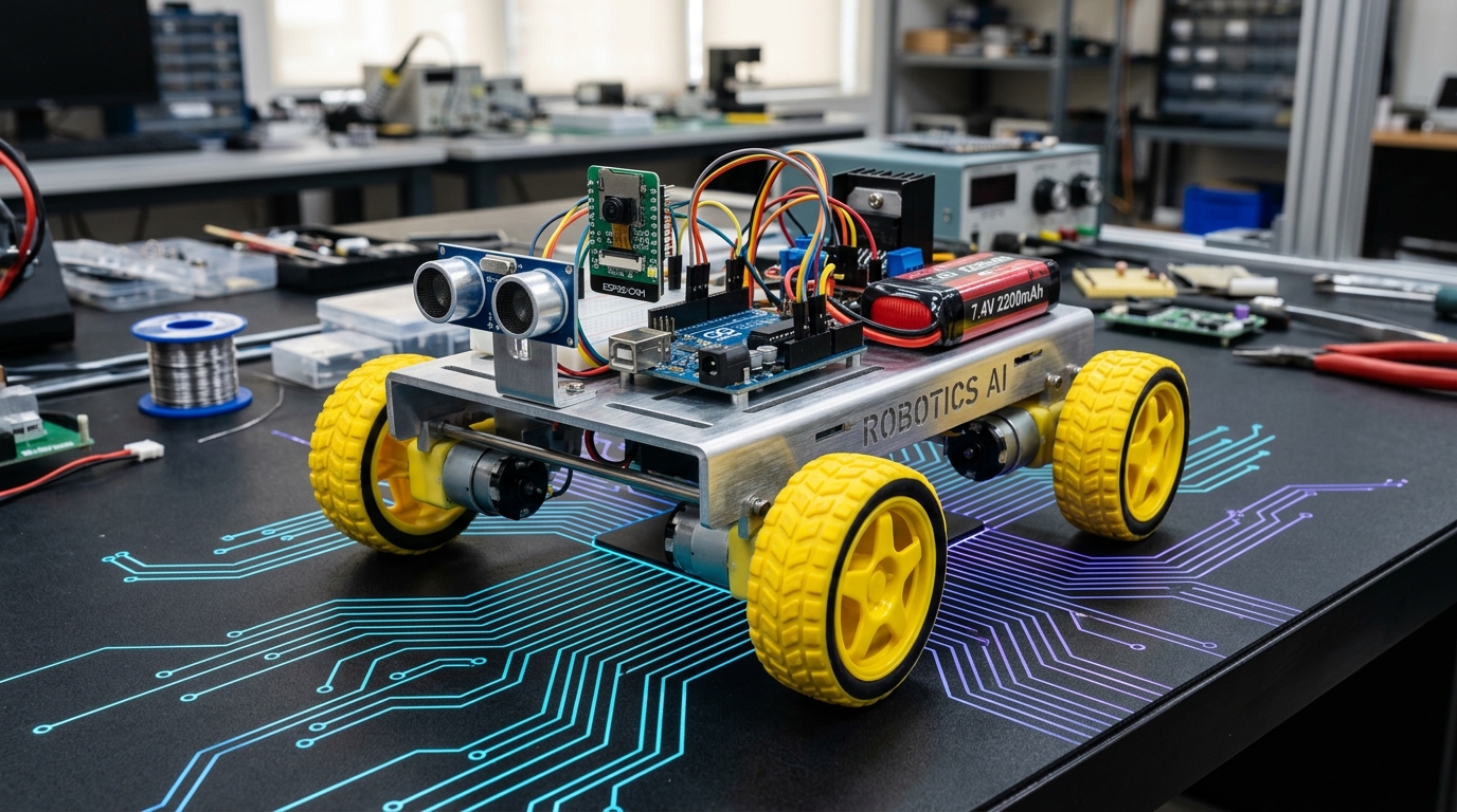
High-Speed Line Follower Robot with IR Sensor Array & PID Control in Arduino
Line-following competitions test precision sensor calibration and mathematical control loop tuning. Basic bang-bang control results in sharp oscillations and wheel shudder. By implementing a full Proportional-Integral-Derivative (PID) algorithm, the robot anticipates turns, decelerates into sharp chicanes, and accelerates along straightaways.
1. Hardware Requirements
- 1× Arduino UNO or Nano
- 1× 5-Channel or 3-Channel TCRT5000 IR Sensor Array
- 1× L298N or TB6612FNG Dual DC Motor Driver
- 2× High-RPM Micro Metal Gearmotors (100–300 RPM)
- 1× Lightweight Acrylic / 3D-Printed Chassis & Caster
2. PID Algorithm Implementation
cppfloat Kp = 25.0;
float Ki = 0.0;
float Kd = 15.0;

int P = 0, I = 0, D = 0, previousError = 0;
int baseSpeed = 150;

void calculatePID(int error) {
  P = error;
  I = I + error;
  D = error - previousError;
  previousError = error;

  int correction = (Kp * P) + (Ki * I) + (Kd * D);

  int leftSpeed = constrain(baseSpeed + correction, 0, 255);
  int rightSpeed = constrain(baseSpeed - correction, 0, 255);

  setMotorSpeeds(leftSpeed, rightSpeed);
}
Parts used in this tutorial
Buy them in one click — ships from Pune across India.
- Arduino UNOMicrocontrollers₹265.58+ GST
- IR Obstacle Avoider SensorSensors₹33.39+ GST
- L298N 2A Based Motor Driver ModuleMotors & Actuators₹135.00+ GST
- DC Plastic Gear Motor with Wheel (BO)Motors & Actuators₹75.88+ GST


Approx. total ₹509.85 (before GST)Add all to cart
#robotics#line-follower#sensors
Found this useful? Tell us what you'd like to read next via our RFQ form.