
All products · 8 of 1440
Electronics, sensors, robotics kits, PC components, peripherals — everything Unik Systems carries, in one place.
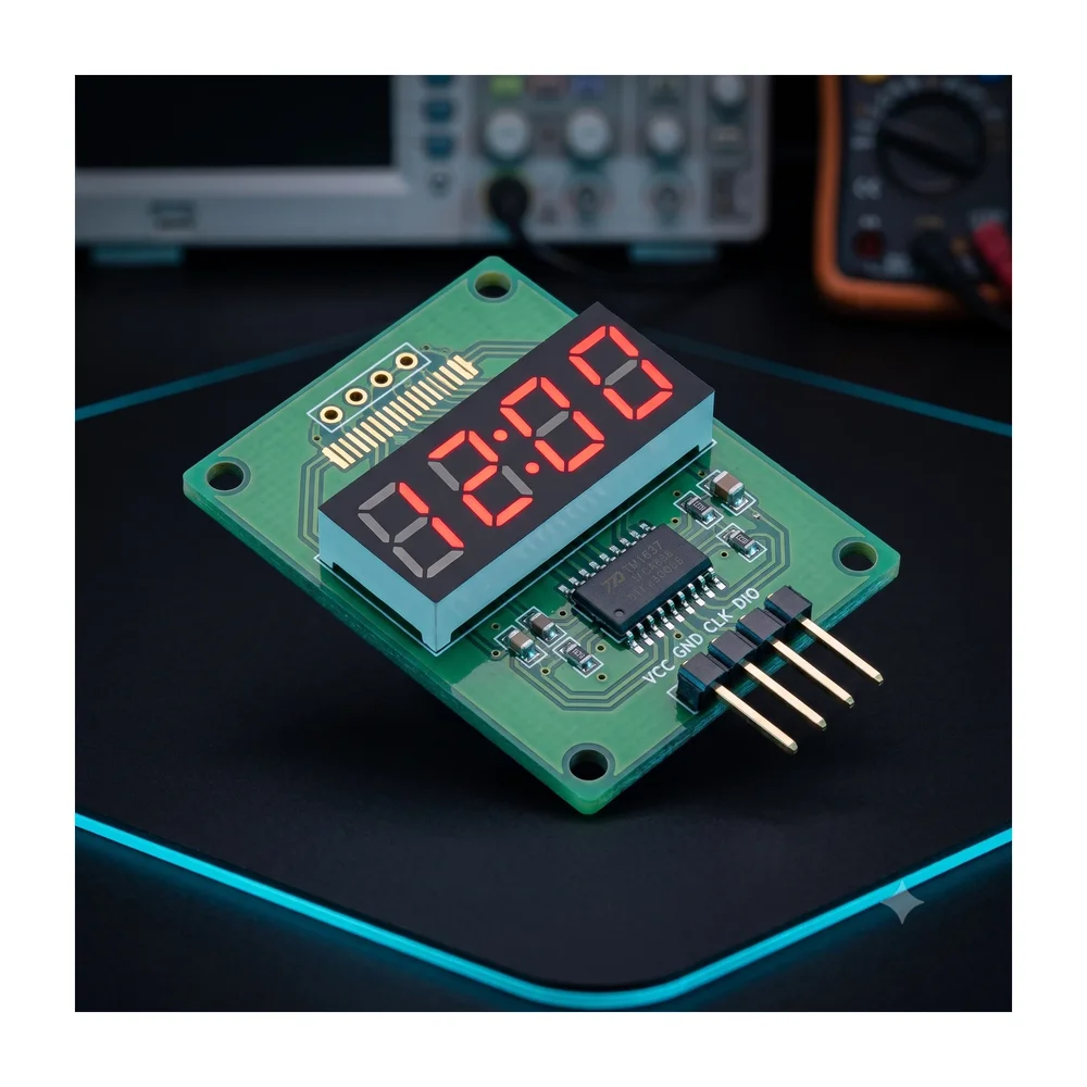
7-Segment LED Display (4-digit)
LED 4-digit display module with clock point, 4-pin Dupont line for Arduino.
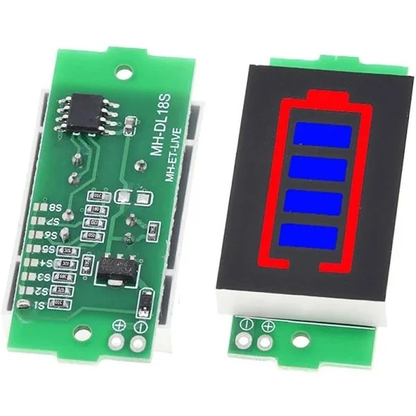
1S to 8S Battery Level Indicator Module For Li-ion Battery
[Li-Ion Capacity Indicator] Description: This is a 1S-8S Battery Capacity Indicator Module. The charge status (capacity) of 18650 Lithium-ion batteries and other lithium batteries with a maximum voltage of 4.2 volts per cell can be quickly visualized using these modules. This 1S-8S Battery Capacity Indicator module is ideal for DIY power supply, battery chargers, RC, and electric cars, as 1S-8S Battery Capacity Indicator displays the voltage state of the battery in a rapid and easy-to-read manner. Simply connect the 1S to 8S Battery Level Indicator module to the positive and negative contacts of your battery or battery pack, and a visible bar display shows the charge status of the battery in real-time. The 1S-8S Battery Capacity Indicator Display bars are Green, and the display outline is red. 1S-8S Battery Capacity Indicator can be used as an indicator for 1 to 8 cells or 1S to 8s Battery Pack and is user-configurable with a jumper pad setting. 1S-8S Battery Capacity Indicator has a Compact design with 4-segment display. Specifications: Number of Cells: 1~8S Number of cell Pre-set Setting: 1 Cell Indicator Type: 4 Bar Graph Operating Voltage: 3V-34VDC Operating Current: 5mA Operating Temperature: 10℃~65℃ Color: Blue and Outline red How to Use: Connect the positive and negative terminals of the display panel to the positive and negative terminals of the tested battery in parallel, and the digital tube not only displays the real-time battery power. Display power quantity parameters: (Note: N represents the number of batteries) When the battery voltage exceeds N*3.3V, it will illuminate 1 battery When the battery voltage exceeds N*3.5V, it will illuminate 2 pieces of electricity When the battery voltage exceeds N*3.7V, it will illuminate 3 pieces of electricity When the battery voltage exceeds N*3.9V, it will illuminate 4 pieces of electricity When the battery voltage is less than N*3.3V, the 4 displays will be turned off Package Included: 1 x 1S-8S Battery Capacity Indicator 1S to 8S Battery Level Indicator Module – Li-ion Battery Level Indicator *product image for illustration purposes only. actual product may vary.
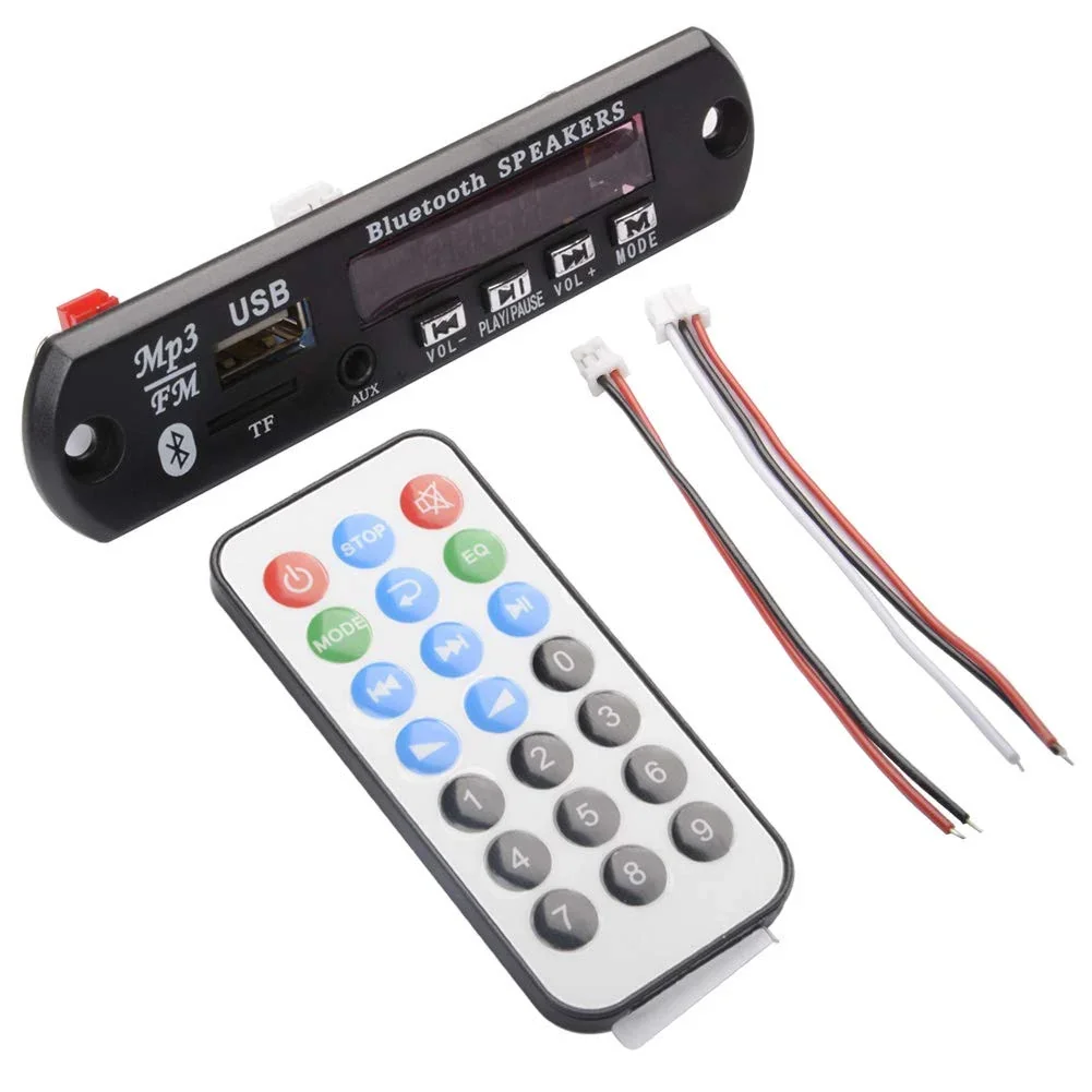
Bluetooth MP3 Decoding Board Module with inbuilt SD Card Slot / USB / FM / and Remote Control
[Audio, Audio Receiver] Bluetooth MP3 Decoder Board Module with USB, SD Card, FM Radio, AUX & Remote Control The Bluetooth MP3 Decoder Board Module is a compact and versatile multimedia audio player designed to add multiple audio playback options to DIY speakers, amplifier systems, home theaters, car audio systems, portable speakers, and custom audio projects. It combines Bluetooth, USB, SD/TF card, AUX input, and FM radio functions in a single convenient module. The module can be connected to a compatible audio amplifier board to create a complete multimedia audio system. It features a clear LCD display for displaying playback information, input mode, track details, and FM frequency. An included IR remote control allows convenient wireless operation from a distance. With support for popular audio formats including MP3, WMA, WAV, FLAC, and APE, the module provides flexible playback options for different music sources. ⭐ Key Features Bluetooth wireless audio receiver Built-in USB port for music playback Built-in SD/TF card slot FM radio function AUX audio input Supports USB / SD / Bluetooth / FM / AUX source selection Stereo digital audio output LCD display for playback information Includes IR remote control Supports folder selection and organized playback Supports Bluetooth stereo audio Hands-free calling support as specified Compact design for easy installation Suitable for DIY audio projects 📋 Technical Specifications Product Type: Bluetooth MP3 Decoder Board Bluetooth: Bluetooth Audio Receiver Audio Output: Stereo Digital Audio Output Input Sources: Bluetooth / USB / SD (TF) Card / AUX / FM USB Support: Yes SD/TF Card Slot: Yes FM Radio: Yes AUX Input: Yes Display: Seven segment Display Remote Control: IR Remote Included Audio Formats: MP3 / WMA / WAV / FLAC / APE Bluetooth Function: Wireless Audio Playback / Hands-Free Calling Playback Function: Folder Selection & Music Playback Installation: Audio Amplifier / DIY Speaker System Application: DIY Speakers, Home Theater, Car Audio, Portable Audio Systems Mounting Type: Panel / Enclosure Mount Power Supply: Refer to the specific module version before connection Output Connection: Connect to a compatible amplifier input Module Type: Multi-Function Audio Decoder Board 🔧 Applications DIY Bluetooth Speakers Portable Speaker Systems Home Theater Upgrades Car Audio Modification Amplifier Projects Multimedia Speaker Repair Custom Audio Systems DIY Music Players Portable Audio Systems Electronic Audio Projects 🛠️ How It Works The module works as a multi-function audio source and decoder. Select Bluetooth, USB, SD/TF card, AUX, or FM radio as the required audio source. The module decodes the selected audio signal and provides a stereo audio output that can be connected to a compatible amplifier board. For a DIY speaker project, connect the decoder module to a suitable amplifier and then connect the amplifier to the speakers. The included IR remote can be used to control playback, mode selection, track selection, volume, and other supported functions. 🔌 Installation Connect the module to a compatible power supply according to the specifications of the particular module version. Connect the audio output to the input of a suitable amplifier board and connect the amplifier output to the speakers. Insert a compatible USB drive or SD/TF card containing supported audio files, or pair the module with a Bluetooth device. AUX input and FM radio can also be selected using the module controls or remote control. 📦 Package Includes 1 × Bluetooth MP3 Decoder Board Module with USB / SD / FM / AUX 1 × IR Remote Control 1 × Power & Signal Connecting Cable ⚠️ Precautions This module is not recommended for beginners without basic electronics knowledge. Check the module's required supply voltage and polarity before powering it. Ensure all wiring is correct before switching on the power. Connect the audio output to a compatible amplifier input. Do not connect speakers directly to the decoder output unless confirmed by the specific module version. Avoid short circuits between power and signal connections. Do not expose the board to water or excessive moisture. We are not responsible for damage caused by incorrect wiring, improper installation, or misuse.
 Out of stock
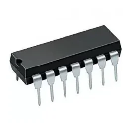
74HC47 or 74LS47 IC BCD to seven segment decoder driver
[Logic Gates IC] 7447 or 74LS47 decodes BCD into 7 Segments, which means it accepts a binary coded decimal or BCD Values as input and decoded into a pattern that drives a 7-segment for displaying digits 0 to 9, so its name is BCD to 7 segment driver or decoder. Its input is 4 lines BCD data and generates complements as output. The generation of complement data of BCD is internally so no coding or programming is required to generate it. Specification Large Voltage range Has open collector output which directly drives indicator Has a wide range of operating conditions No need for external resistors because of internal pull-ups No high-speed termination because of the input clamp diode 4 the number of input lines and 7 output lines Pin Description BCD input 2 BCD input 3 LT RBO RBI BCD input 4 BCD input 1 GND E D C B A G F VCC
 Out of stock
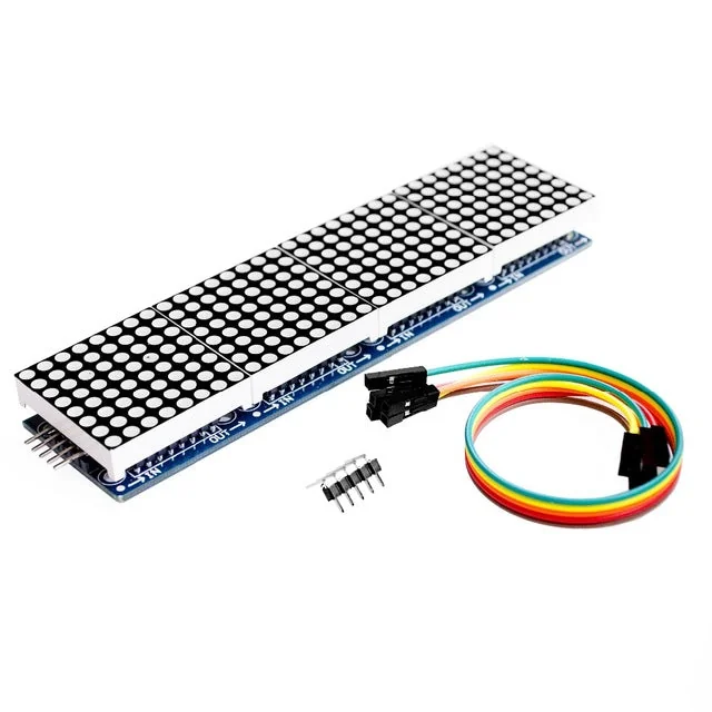
MAX7219 Dot Matrix 4 in 1 Display Module
[LED/LCD Display Module] Features – Driver Chip: MAX7219 Input Voltage: 3.7 to 5.3 V Input Current: 320 mA Display Dimensions: 32x32x6 (LxWxH) mm PCD Dimensions: 128×32 (LxW) mm — MAX7219 4-in-1 Display Dot Matrix Module is an integrated serial input/output common-cathode display driver, it connects the microprocessor 7-segment digital LED display with 8 digits, you can also connect a bar graph display or 64 independent LED. Thereon including a B-type BCD encoder chip, multi-channel scanning loop segment word driver, but also a static RAM 8 x 8 for storing each data. Only one external register is used to set the segment current of each LED. Specifications :- Dimensions: 128 x 32 x 1.5cm(LxWxH)(All 4 in 1) Dimension 32 x 32 x 1.5 cm (LxWxH) (Single Module) A single module can drive an 8×8 dot matrix common cathode Operating voltage: 5V Weight: 55 gm Fixing screws with 64 holes with a diameter 3mm Module with input and output interfaces Support for cascading multiple modules Wiring Instructions:- The left side of the module to the input port, the right to an output port. When the control of a single module, simply input port connected to CPU When a plurality of cascaded modules, input and output termination CPU, an input terminal of the second output end of the first module a module, the first two modules of the input terminal of the three termination modules, and so on.. Pin Description:- VCC 5V GND GND DIN P2.2 CS P2.1 CLK P2.0
 Out of stock
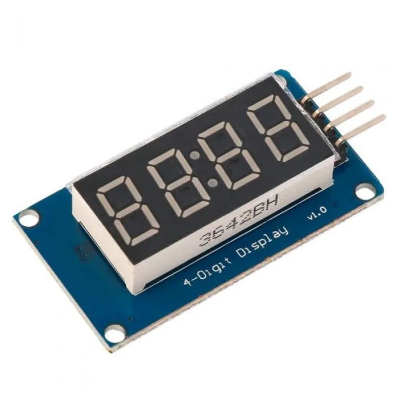
TM1637 4 Digits 7 Segment Led Display Module with Clock for Arduino
[LED/LCD Display Module] The TM1637 4 Digits 7 Segment Led Display Module with Clock for Arduino is an affordable solution for displaying the output data of your Arduino project. Though the data displayed is restricted by numbers still it allows users to display some characters too like A, B, C etc. This 7 segment LED Display has 4 digits which are controlled by TM1637 Driver Chip. It requires only two connections to control this TM1637 4 Digits 7 Segment Led Display Module. Also thanks to the I2C Bus you can control it using only 2 wires, leaving more pins available on your MicroController to connect other things. The module is a 12-foot clock with four common anode tube (0.36 inch) display module for driver IC TM1637, only two signal lines can make the MCU control four 7-segment digital tubes. .Pinout Description of TM1637 4 Digits 7 Segment Led Display Module with Clock for Arduino :- LED Display module to Arduino- GND – GND Vcc – 5V DIO – D2 CLK – D3 Features of TM1637 4 Digits 7 Segment Led Display Module with Clock for Arduino:- Ease to use. Ease of multiplexing. Can use as a 4 digit display unit. Can use as a clock display. DIY clock project. 4 digit display unit. Electrical/Electronic projects. The counter project using 7 segment display. 4 M2 screws positioning holes for easy installation Package Includes:- 1 x TM1637 4 Digits 7 Segment Led Display Module with Clock for Arduino. * Product Images are shown for illustrative purposes only and may differ from actual product.
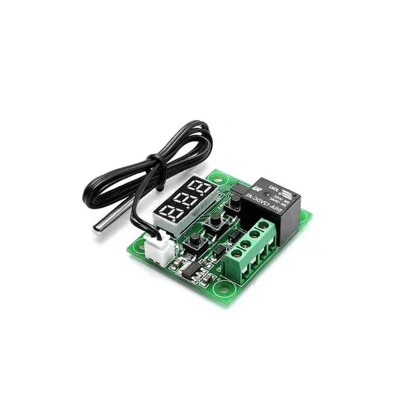
W1209 Digital Temperature Controller Thermostat Module with Display and Waterproof Temperature Sensor
[Temperature Sensor] XH W1209 12V Digital Temperature Control Module + Display and NTC Temp Sensor This is XH W1209 digital temperature controller Module W/ Display and NTC Waterproof Temperature Sensor. W1209 Mini thermostat Temperature controller is low-cost 12V Temperature controller with 7-segment display and 3 switch keypad for setting temperature and other parameters. The module features an NTC thermistor temperature sensing and has an accuracy of 0.1 C. The XH W1209 digital temperature controller Module W/ Display and NTC Waterproof Temperature Sensor is an incredibly low cost yet highly functional thermostat controller. With this module, you can intelligently control power to most types of electrical device based on the temperature sensed by the included high accuracy NTC temperature sensor. Although this module has an embedded microcontroller no programming knowledge is required. 3 tactile switches allow for configuring various parameters including on & off trigger temperatures. The onboard relay can switch up to a maximum of 240V AC at 5A or 14V DC at 10A. We can display current temperature in degrees Centigrade via its 3 digit seven segment display and the current relay state by an onboard LED. DISPLAYING THE CURRENT TEMPERATURE The thermostat will display the current temperature in °C by default. When in any other mode making no input for approximately 5 seconds will cause the thermostat to return to this default display. SETTING THE TRIGGER TEMPERATURE To set the trigger temperature press the button marked ‘SET’. The seven-segment display will flash. You can now set a trigger temperature (in °C) using the ‘+’ and ‘-‘ buttons in 0.1° increments. If we didn’t press any buttons for approximately 2 seconds the trigger temperature will be store and the display will return back to the current temperature. SETTING THE PARAMETERS To set any parameter first long press the ‘SET’ button for at least 5 seconds. The seven-segment display should now display ‘P0’. This represents parameter P0. Pressing the ‘+’ or ‘-‘ buttons will cycle through the various parameters (P0 to P6). Pressing the ‘SET’ button whilst any of these parameters are displayed will allow you to change the value for that parameter using the ‘+’ and ‘-‘ buttons. When finished setting a parameter press the set button to exit that option. If no buttons are pressed for approximately 5 seconds the thermostat will exit the parameter options and will return back to the default temperature display. SETTING THE COOLING OR HEATING PARAMETER P0 The parameter P0 has two settings, C and H. When setting to C (default) the relay will energize when the temperature is reached. Use this setting if connecting to an air-conditioning system. When set to H the relay will de-energize when the temperature is reached. Use this setting if controlling a heating device. SETTING THE HYSTERESIS PARAMETER P1 This sets how much change in temperature must occur before the relay will change state. For example, if set to the default 2oC and the trigger temperature has been set to 25oC, it will not de-energize until the temperature falls back below 23oC. Setting this hysteresis helps stop the thermostat from continually triggering when the temperature drifts around the trip temperature. SETTING THE UPPER LIMIT OF THE THERMOSTAT PARAMETER P2 This parameter limits the maximum trigger temperature that can be set. It is useful as a safety to stop an excessively high trigger temperature from accidentally being set by the user. SETTING THE LOWER LIMIT OF THE THERMOSTAT PARAMETER P3 This parameter limits the minimum trigger temperature that can be set. It is useful as a safety to stop an excessively low trigger temperature from accidentally being set by the user. SETTING TEMPERATURE OFFSET CORRECTION PARAMETER P4 Should you find there is a difference between the displayed temperature and the actual temperature; (for instance, if the temperature probe is on a long run of cable) you can make minor corrections to the temperature reading with this parameter. SETTING THE TRIGGER DELAY PARAMETER P5 To reach trigger temperature this parameter allows for delaying switching of the relay. The parameter can be set in one-minute increments up to a maximum of 10 minutes. SETTING THE HIGH-TEMPERATURE ALARM PARAMETER P6 Setting a value for this parameter will cause the relay to switch off when the temperature reaches this setting. The seven-segment display will also show ‘—‘ to indicate an alarm condition. The relay will not re-energize until the temperature falls below this value. The default setting is OFF.
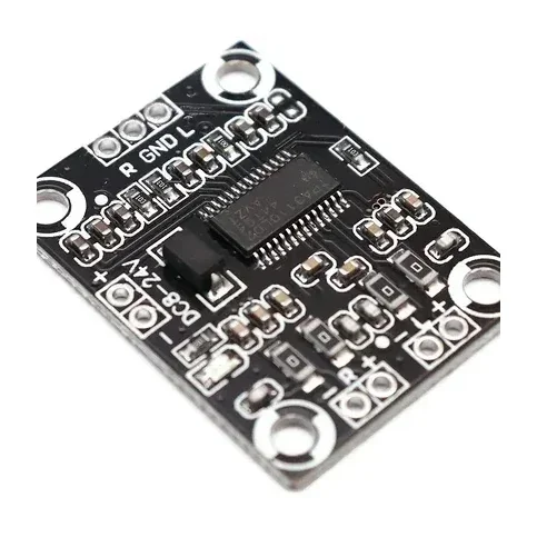
TPA3110 30W (15W+15W) Digital Stereo Audio Power Amplifier Board Module CA-3110
[Amplifier Board] The TPA3110/HDX8816A is a 2×15 Watt Class D Power Amplifier Board. It is designed to drive Professional Stereo Audio Speakers. This Amplifier Board is mostly used with 8-ohm speakers but it can successfully drive the speaker as low as 4 ohm. It's a very high efficient board which eliminates the need of using a heat sink. This device is fully protected against the shorts to GND, VCC & Output to Output. The Application of this device is endless in the segment of consumer electronics. Its most common and widely used application is in Televisions and mid-range compact audio equipment. Features : Wide range in Input voltage Source i.e. from 8v to 24v. It can be used for applications like cars, vehicles, computer speakers, family audio and video systems, and in your own DIY Music System. This amplifier board comes with 4 mounting holes, which is very helpful in tightening the complete circuit board according to your project requirement. 3110 power amplifier chip does not require a heat dissipation sink. It has over-current and over-heat protection. Specification : Operating voltage range: 8V to 24V Amplifier chip: TPA3110 / HDX8816A Output power: 2 x 15W Dimension: 25mm x 33mm x 3mm Package includes: 1x TPA3110 30W (15W+15W) Digital Stereo Audio Power Amplifier Board Module