
All products · 5 of 1440
Electronics, sensors, robotics kits, PC components, peripherals — everything Unik Systems carries, in one place.
 Out of stock
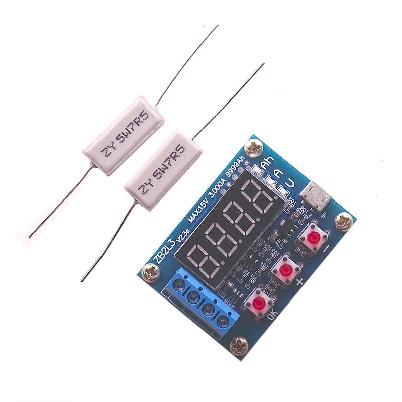
ZB2L3 18650 Li-ion Lithium Lead-acid Battery Capacity Meter Discharge Tester Analyzer
[Battery Capacity Tester] Description: Material: Electrical components Color: See pictures ZB2L3 battery capacity tester discharge type 1.2-12V external load capacity of the battery and other tests 18650 Tools, single-function, by controlling the load off and get real-time integrated discharge current capacity results Maximum support 15V 3A discharged through the discharge voltage and current, itself does not discharge Maximum capacity statistics support 9999Ah (9999000mAh) Automatically identifying and developing appropriate battery termination voltage can also be manually adjusted Specifications: Power supply voltage: DC4.5-6V (micro USB connector) Operating Current: less than 70mA Discharge voltage: 1.00V-15.00V 0.01V resolution Termination voltage range: 0.5-11.0V Supported by current: 3.000A 0.001A resolution Maximum voltage measurement error: 1% + 0.02V Maximum current measurement error: 1.5% + – 0.008A Maximum battery capacity range: 9999Ah (1Ah = 1000mAh) greater value by shifting the decimal point to switch, when the display is less than 10Ah X.XXX, as shown above to achieve 10Ah XX.XX, and so on. Board size: 50mmX37mm Finished Size: 50mmX37mmX17mm (length X width X height maximum position size, contains copper foot height) Instructions: 1. The first test should be a fully charged battery. 2. Connect the battery to be tested positive to positive input, a negative input to the negative, can not be reversed (with load reversal may damage the circuit)! Load connected to the output of the positive and negative output, to work through the tester micro USB power supply (not available desktop or laptop USB powered), then the battery voltage. 3. Direct start test need only one press of the “OK” button, the tester can automatically develop an appropriate termination voltage of the battery full charge voltage, and will start flashing after the test three times. Need to develop artificial termination voltage only when the battery voltage display state by pressing “+” or “-” buttons to modify the termination voltage display beginning with P, behind the representative voltage resolution 0.1V, set up after pressing the “OK “start testing. 4. After the start of the test the tester will control the load of the electronic switch is turned on, the test data shows that the process will release capacity (Ah), current discharge current (A) and battery voltage (V) between the wheel was. When the battery voltage reaches the set cut-off voltage, load control switches off the tester display data stays in capacity (Ah) and above and the corresponding indicator flashes quickly together, now displays the actual capacity of the battery is discharging capacity, about the press “OK” to terminate flashing allows stable data display, press again “OK” button to return to the power-on state can just replace the battery test the next section …… Error codes and their meanings: Err1: battery voltage is above 15V Err2: battery voltage is lower than the termination voltage Err3: Battery can not afford to load or discharge current line too much resistance Err4: overcurrent (current exceeds 3.1A) Err5:Improper use or incorrect wiring has caused the device to be burned out and cannot be used (current sampling or control switch MOS burned out). Note: Use the resistance of the discharge process, resistive load will seriously heat, please pay attention to safety! This circuit voltage in order to improve the measurement accuracy, specially designed DC bias, when the terminal displays nothing then a small voltage does not affect the actual measurement, if you are shorting the input terminals (absolute 0V) will show 0 No retail package Quantity:1Pc Due to the difference between different monitors, the picture may not reflect the actual color of the item. Thank you!! Package Content: 1Pc x battery capacity tester 2Pc x Load resistor Power Battery Capacity Tester LED Display Micro USB Li-ion Lithium 18650 External Load Battery Discharge Testing Analyzer
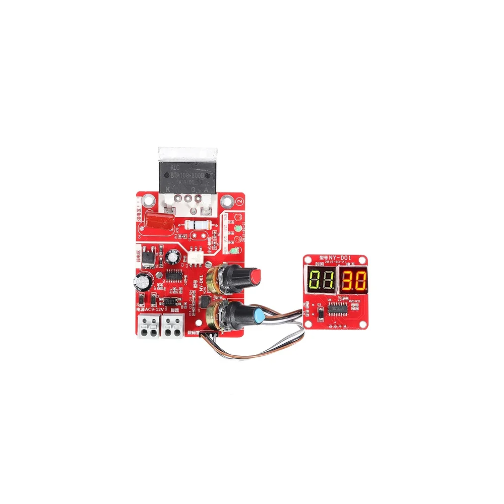
NY-D01 100A Digital Display Spot Welding Controller Board
[Spot Welding Parts] The principle of silicon-controlled phase shifting triggering is adopted to adjust the time and the current to achieve welding. With a digital display, you can directly see the time and current. Optocoupler isolates the strong and weak electricity, making the operation safer. Using a high-precision single potentiometer to ensure reliable and convenient input. The design of a reliable zero-crossing detection circuit ensures the SCR phase shift accuracy. Made of high-quality PCB, the control board is long-lasting. The module is 8cm long, 6cm wide, and 2cm high. It is developed for DIY or simple resistance welding. Features: 1 The use of STM8 industrial control center microcontroller. 2 Strong and weak electricity through optocoupler insulation, safe operation. 3 The power line and foot switch line adopts the bolt the quick connect terminal, more convenient and reliable. 4 Input time, current using a high-precision simple potentiometer, to ensure reliable, convenient input 5 On-board power supply, state, foot, trigger indicator, work status clearly visible. 6 The design of reliable zero-crossing detection circuit to ensure that the SCR phase shift accuracy. 7 The controller is compatible with 100A scr. 8 Digital control interface, you can display the current time and current settings. 9 Input time of 1-50, cycle unit (1 cycles is 20 ms), current input (30-99%), Material Plastic+Metal Current Input 30-99% Microcontroller. STM8 Time input 1-50 Shipping Weight 0.12 kg Shipping Dimensions 8 × 6 × 2 cm Package Includes: 1 x NY-D01 100A Digital Display Spot Welding Controller Board
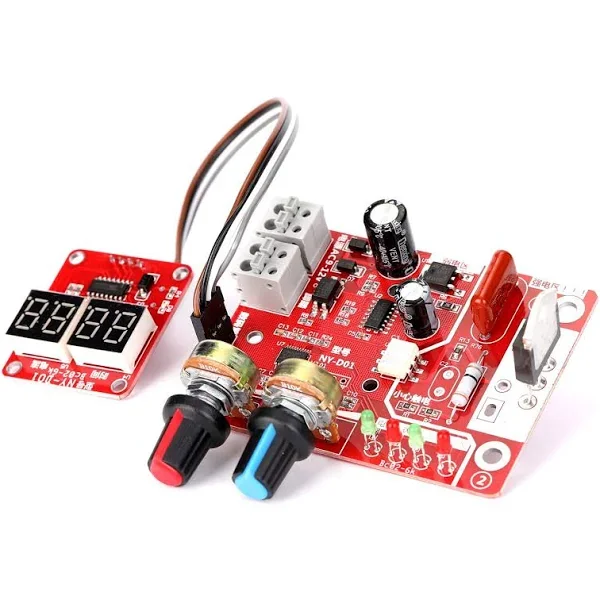
NY-D01 40A Digital Display Spot Welding Controller Board
[Spot Welding Parts] This is a NY-D01 40A Digital Display Spot Welding Controller Board. The principle of silicon controlled phase shifting triggering is adopted to adjust the time and the current to achieve welding. With a digital display, you can directly see the time and current. Optocoupler isolates the strong and weak electricity, making the operation safer. Using a high-precision single potentiometer to ensure reliable and convenient input. The design of a reliable zero-crossing detection circuit ensures the SCR phase shift accuracy. Made of high-quality PCB, the control board is long-lasting. The module is 8cm long, 6cm wide and 2cm high. It is developed for DIY or simple resistance welding. Connection Diagram: Features: 1 The use of STM8 industrial control centre microcontroller. 2 Strong and weak electricity through optocoupler insulation, safe operation. 3 The power line and footswitch line adopts the bolt the quick connect terminal, more convenient and reliable. 4 Input time, current using a high-precision simple potentiometer, to ensure reliable, convenient input 5 On-board power supply, state, foot, trigger indicator, work status clearly visible. 6 The design of a reliable zero-crossing detection circuit to ensure that the SCR phase shift accuracy. 7 The controller is compatible with 40A SCR. 8 Digital control interface, you can display the current time and current settings. 9 Input time of 1-50, cycle unit (1 cycles is 20 ms), current input (30-99%), Package Includes: 1 x NY-D01 40A Digital Display Spot Welding Controller Board
 Out of stock
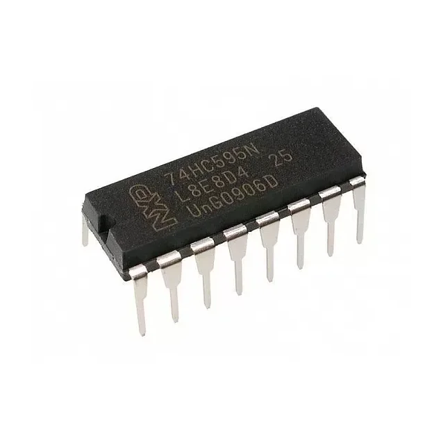
74HC595 Serial to Parallel Shifting IC
[Logic Gates IC] DESCRIPTION:- The 74HC595N is a simple 8-bit shift register IC. Simply put, this shift register is a device that allows additional inputs or outputs to be added to a microcontroller by converting data between parallel and serial formats. Your chosen microprocessor is able to communicate with The 74HC595N using serial information then gathers or outputs information in a parallel (multi-pin) format. Essentially it takes 8 bits from the serial input and then outputs them to 8 pins. This small DIP packaged IC contains an 8-bit, serial-in-parallel-out shift register that feeds an 8-bit D-type storage register with parallel 3-state outputs. Pin Configuration:- Pin Number Pin Name Description 1,2,3,4,5,6,7 Output Pins (Q1 to Q7) The 74hc595 has 8 output pins out of which 7 are these pins. They can be controlled serially 8 Ground Connected to the Ground of the circuit 9 (Q7) Serial Output This pin is used to connect more than one 74hc595 as cascading 10 (MR) Master Reset Resets all outputs as low. Must be held high for normal operation 11 (SH_CP) Clock This is the clock pin to which the clock signal has to be provided from MCU/MPU 12 (ST_CP) Latch The Latch pin is used to update the data to the output pins. It is active high 13 (OE) Output Enable The Output Enable is used to turn off the outputs. Must be held low for normal operation 14 (DS) Serial Data This is the pin to which data is sent, based on which the 8 outputs are controlled 15 (Q0) Output The first output pin. 16 Vcc This pin powers the IC, typically +5V is used. Features :- 8-bit, Serial In – Parallel out Shift register Operating Voltage: 2V to 6V Power Consumption: 80uA Output source/sink current: 35mA Output Voltage is equal to Operating voltage Minimum high-level Input Voltage: 3.15V @(Vcc=4.5V) Maximum low-level Input Voltage: 1.35V @(Vcc=4.5V) Can be easily cascaded with more IC to get more outputs Maximum Clock Frequency: 25Mhz @4.5V Available in 16-pin PDIP, GDIP, PDSO packages Where to Use 74HC595 IC:- The 74HC595 is an 8-bit Serial In – Parallel Out Shift Register, i.e. it can receive (input) data serially and control 8 output pins in parallel. This comes in very handy where do not have enough GPIO pins on our MCU/MPU to control the required number of outputs. It is often used in projects where relatively a large number of LED's has to be controlled through the Microcontroller. It can also be used to interface LCD screen since they can acts as the data bit for the LCD displays. It can also be used to control 5V loads like relays through a 3.3V microcontroller since the high-level voltage is only 3.15. So if you are looking for an IC to save on your GPIO pins on the Microcontroller then this IC might be the right choice for you. How to Use a 74HC595 IC:- The 74HC595 shift register is commonly used with microcontrollers or microprocessors to expand the GIPO functionalities. It requires only 3 pins connected to the MCU, which are Clock, Data and Latch. It has a wide operating voltage from 2V to 6V. An application circuit of the IC is shown below: Package Includes:- 1 x 74HC595 IC
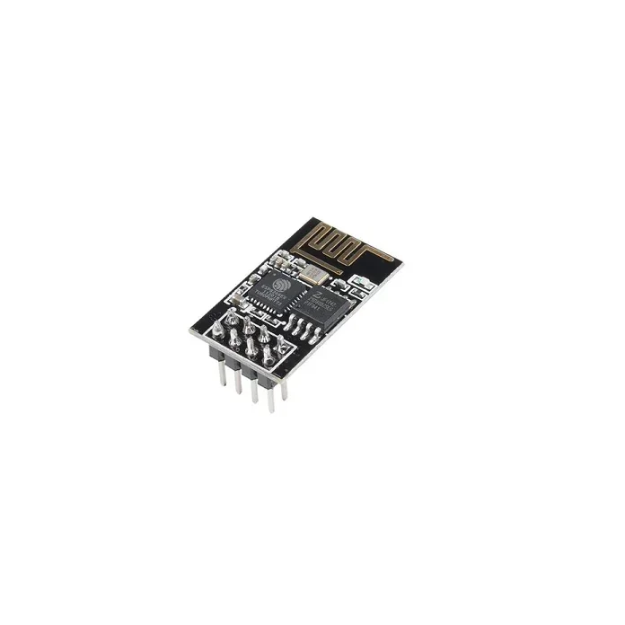
ESP-01 ESP8266 Serial WIFI Wireless Transceiver Module
[ESP Modules] The ESP 01 ESP8266 Serial WIFI Wireless Transceiver Module is a self-contained SOC with integrated TCP/IP protocol stack that can give any microcontroller access to your WiFi network. The ESP8266 is capable of either hosting an application or offloading all Wi-Fi networking functions from another application processor. Each ESP8266 module comes pre-programmed with an AT command set firmware, meaning, you can simply hook this up to your Arduino device and get about as much WiFi-ability as a WiFi Shield offers (and that’s just out of the box)! The ESP8266 module is an extremely cost-effective board with a huge, and ever-growing, community. This module has a powerful enough on-board processing and storage capability that allows it to be integrated with the sensors and other application-specific devices through its GPIOs with minimal development up-front and minimal loading during runtime. Its high degree of on-chip integration allows for minimal external circuitry, including the front-end module, which is designed to occupy minimal PCB area. The ESP8266 supports APSD for VoIP applications and Bluetooth co-existence interfaces, it contains a self-calibrated RF allowing it to work under all operating conditions and requires no external RF parts. There is an almost limitless fountain of information available for the ESP8266, all of which has been provided by amazing community support. In the useful links section below you will find many resources to aid you in using the ESP8266, even instructions on how to transforming this module into an IoT (Internet of Things) solution! Note: The ESP8266 Module is not capable of 5-3V logic shifting and will require an external Logic Level Converter. Please do not power it directly from your 5V dev board. This new version of the ESP8266 WiFi Module has increased the flash disk size from 512k to 1MB. Features : Wi-Fi Direct (P2P), soft-AP Integrated TCP/IP protocol stack It features an integrated TR switch, balun, LNA, power amplifier and matching network Equips integrated PLL, regulators, DCXO and power management units Integrated low power 32-bit CPU could be used as an application processor SDIO 1.1 / 2.0, SPI, UART STBC, 1×1 MIMO, 2×1 MIMO A-MPDU & A-MSDU aggregation & 0.4ms guard interval Wake up and transmit packets in < 2ms Standby power consumption of < 1.0mW (DTIM3) Package Includes : 1 x ESP-01 ESP8266 Serial WIFI Wireless Transceiver Module